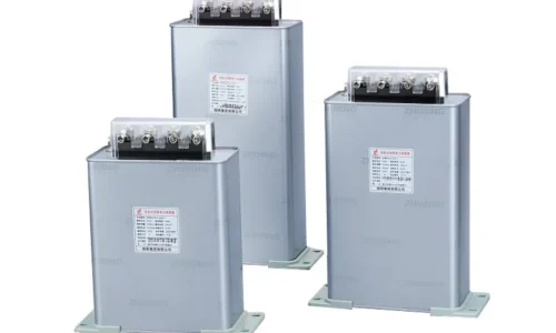
In modern industrial power distribution plants, the components that work most quietly are often the ones most easily overlooked. Quite frequently, a reactive power compensation system is relegated to the most obscure corner of a facility. It is usually ignored until management receives a massive utility bill penalty for a lagging power factor, or a heavy, low-frequency humming sound echoes from the electrical room. In these setups, the central capacitor bank contains no moving parts, which frequently fosters a dangerous operational misconception that it requires zero ongoing maintenance.
In reality, because these devices are subjected to relentless grid fluctuations, heavy loading, and harsh ambient stresses, their internal dielectric insulation experiences irreversible degradation every single hour. Failing to use structured diagnostic protocols to catch these emerging anomalies early can quickly turn minor, hidden capacitance drops into catastrophic facility shutdowns.
İçindekiler
Anatomy of Disaster: Top Causes Behind Capacitor Bank Failure
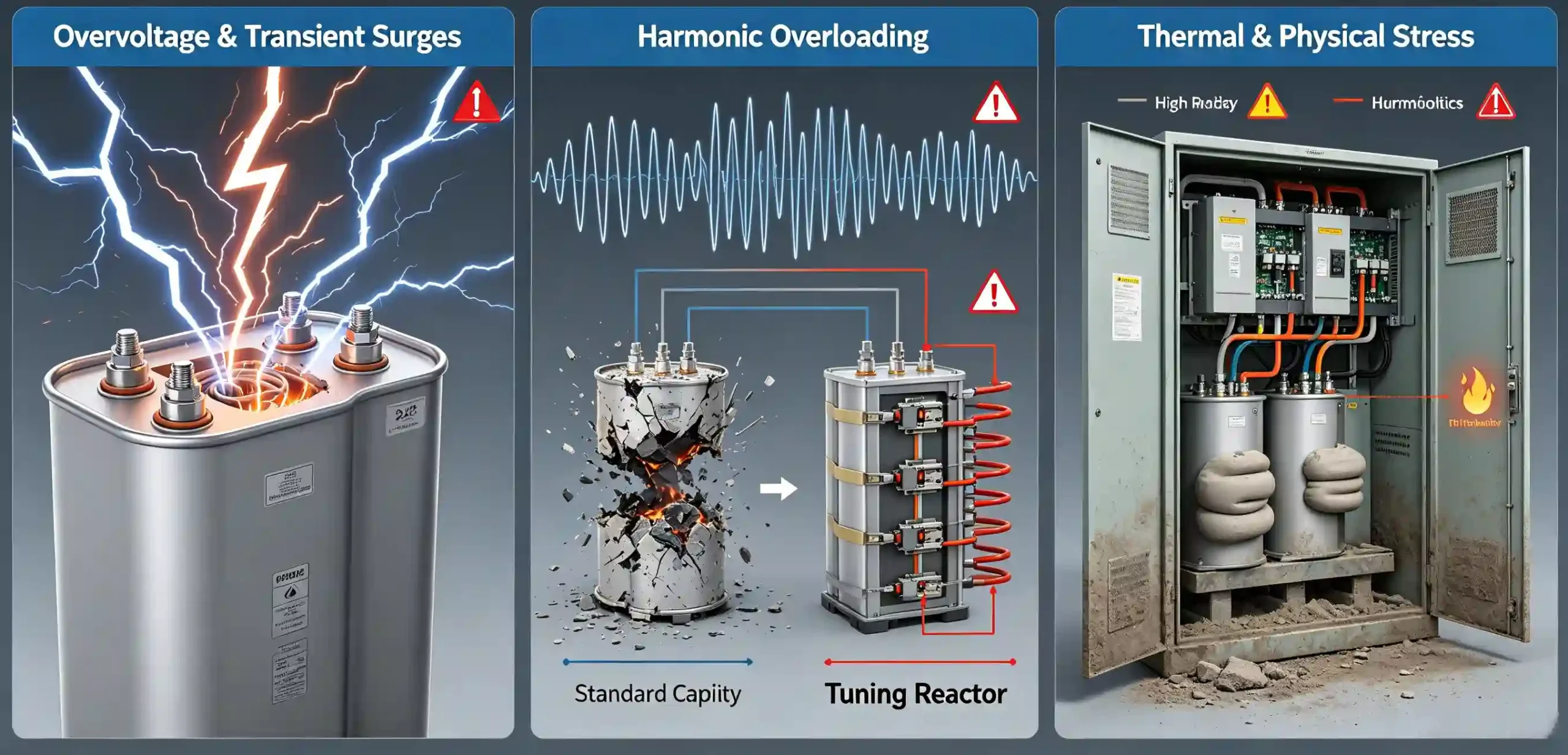
To eliminate the operational risks surrounding a capacitor bank, technicians must first evaluate the underlying root causes driving physical and electrical degradation. Field experience shows that the vast majority of component failures do not stem from initial manufacturing defects, but rather from service conditions exceeding the units’ physical boundaries.
Overvoltage and Transient Surges
Capacitors are exceptionally sensitive to voltage stress. In heavy industrial environments, the routine startup of large induction motors, the unloaded switching of distribution transformers, and external lightning surges inject massive transient overvoltages into the distribution network. While manufacturers build a modest overvoltage cushion into the equipment nameplate, a system running continuously at just ten percent above its nominal voltage rating forces frequent micro-breakdowns within the internal metalized film dielectric. This persistent electrical stress accelerates insulation aging, quickly reducing the total reactive delivery of the system.
Harmonic Overloading
In modern manufacturing facilities filled with variable frequency drives, induction furnaces, and heavy rectifiers, non-linear loads introduce harmonics—the silent killer of electrical insulation. Because a capacitor’s internal opposition to current drops significantly as the frequency of the electrical system climbs, high-frequency harmonic currents pass into the component with extreme ease. This causes severe overcurrent, intense heat dissipation, and a high risk of electrical resonance.
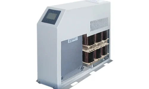
When a standard capacitance step interacts with the upstream inductive properties of transformers and motors, it can create a resonant circuit that amplifies harmonic currents multiple times over. To safely disrupt this resonance and safeguard the internal insulation layers, modern power factor engineering requires installing a specific, heavy-duty reactor in series with the capacitor steps. By altering the resonant frequency of the entire branch, this tuning inductor prevents high-frequency harmonic currents from flooding the capacitor, providing a robust shield against thermal overcurrents.
Thermal and Physical Stress
Excessive heat is the ultimate enemy of dielectric endurance. Capacitors naturally generate internal losses that dissipate as heat during normal operation. If an electrical enclosure features poor ventilation, a failed exhaust fan, or air filters heavily clogged with ambient debris, the internal temperature climbs rapidly. For every temperature increase of roughly eight degrees Celsius above safe limits, the expected life expectancy of the dielectric insulation material is cut in half. Furthermore, if high ambient humidity or conductive industrial dust (such as metallic shavings or carbon particles) settles on the exposed terminal bushings, it can lead to dangerous surface tracking and devastating phase-to-phase short circuits.
Recognizing the Red Flags: Common Failure Modes
When internal degradation inside a capacitor bank passes a critical physical threshold, the equipment exhibits clear physical or electrical warning signs. Well-trained maintenance teams can utilize these early indicators to step in and troubleshoot before minor component wear turns into an absolute circuit emergency.
Casing Bulging and Rupture
Casing deformity is the most obvious visual sign of structural distress. When localized micro-arcing or intense overtemperature causes the internal dielectric oil or impregnating resin to decompose, it releases a high volume of gases, including hydrogen and carbon monoxide. As internal gas pressure expands against the sealed enclosure, the outer aluminum or steel container swells. While modern canisters feature internal overpressure disconnectors designed to break internal connections when the case expands vertically, extremely violent short circuits can still compromise the seams, leaking fluid and creating a substantial fire hazard.
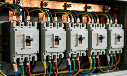
Blown Fuses and Breaker Tripping
When a severe overcurrent state or an absolute internal dielectric short-circuit develops on an individual step, the upstream protective fuses blow instantly or the primary molded-case circuit breaker trips offline. If a routine maintenance check reveals that a specific step’s fuses are consistently failing, simply installing larger replacement fuses is a dangerous mistake. Frequent fuse operations are an explicit indication that the underlying capacitor branch contains a permanent, low-resistance fault path.
Unbalance Current and Parameter Drifts
In large compensation networks where individual capacitor modules are connected in a series-parallel grid, the loss of capacitance in a single module disrupts the phase balance. This unbalance causes unexpected currents to flow through the neutral or bridging connections.
Rather than relying purely on manual visual inspections, modern facilities depend on automatic controllers or digital panel display meter devices mounted on the enclosure door to track real-time phase currents, voltages, and total power factor values. If the digital display reveals a significant phase-current unbalance or an ongoing drop in overall power factor efficiency, it confirms that internal capacitance sections are steadily failing offline.
Step-by-Step Troubleshooting Protocols
When a capacitor bank displays signs of failure, technicians must execute a structured, methodical diagnostic protocol. Handling high-energy storage systems introduces unique electrical hazards that leave no room for rushed or careless shortcuts.
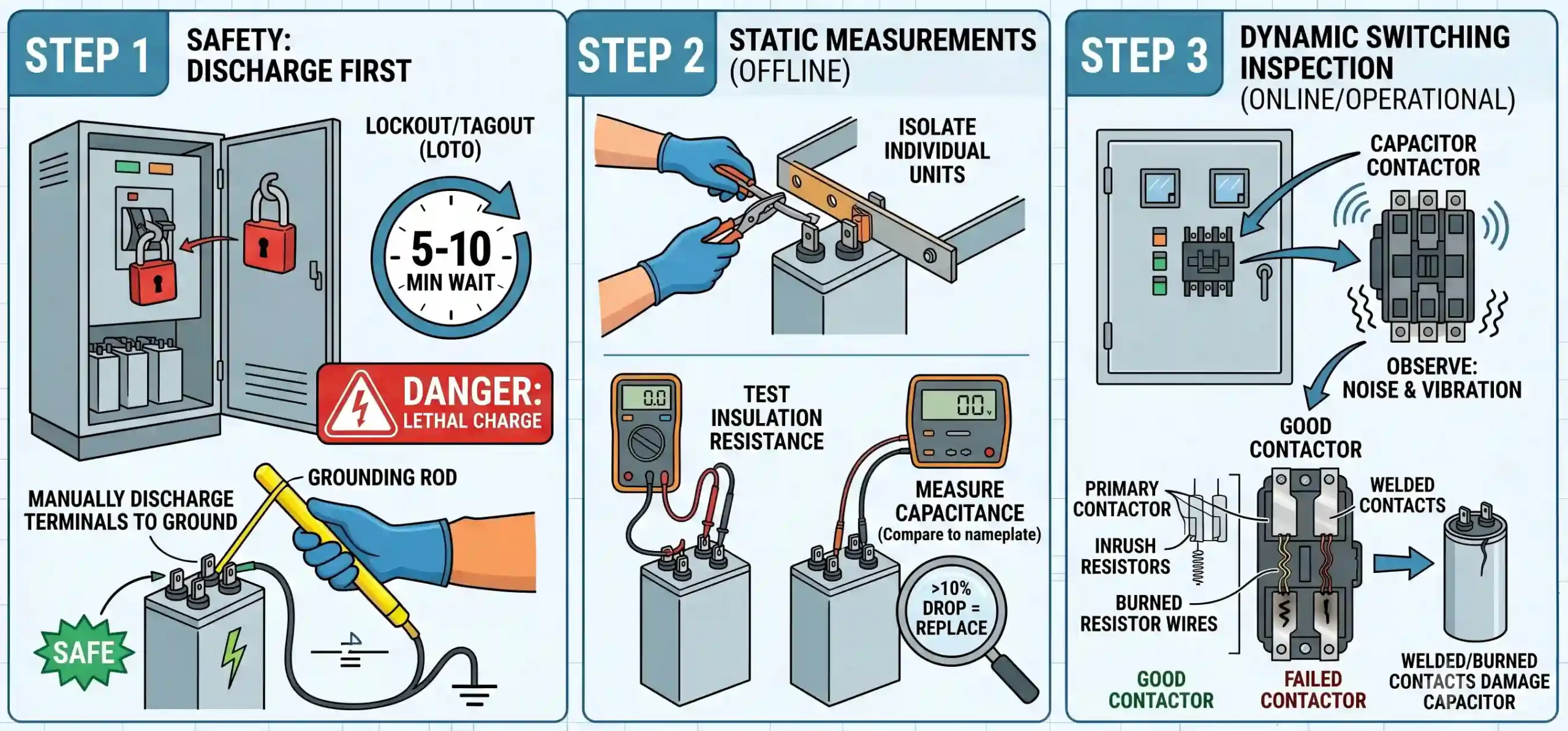
Step 1: The Absolute First Rule—Lockout and Discharge Safety
Capacitors maintain a lethal electrical charge long after the primary power supply is disconnected. Troubleshooting must always begin by executing complete Lockout/Tagout (LOTO) safety procedures and opening the upstream main circuit breaker. Once the circuit is open, technicians must wait a minimum of 5 to 10 minutes to allow the internal discharge resistors to drain the bulk of the stored voltage below safe operating thresholds.
Following this delay, technicians wearing appropriate arc-flash personal protective equipment (PPE) and high-voltage insulation gloves must use a certified grounding rod to manually short-circuit every terminal directly to the station earth ground. This step ensures all residual static electricity is safely neutralized before any physical contact is made with the hardware.
Step 2: Static Offline Measurements
With the system verified dead and safely grounded, disconnect the parallel copper busbars or flexible jumper wires between individual modules to isolate the canisters. Utilize a high-quality digital multimeter and a dedicated capacitance meter to test the insulation resistance between the terminals and the metal enclosure frame. Low resistance readings confirm an active insulation breakdown to ground. Next, measure the capacitance across the phases and compare your findings to the factory nameplate. According to widely accepted facility maintenance guidelines, such as the standards provided by the InterNational Electrical Testing Association (NETA), a canister showing a capacitance drop of more than ten percent from its original rated value must be flagged for immediate replacement.
Step 3: Dynamic Switching Loop Inspection
In some cases, the individual capacitor canisters are perfectly healthy, but the underlying fault stems from the mechanical switching hardware. Automatic power factor systems engage and disengage steps multiple times throughout a typical production day. Engaging a large capacitive load creates heavy inrush currents and voltage transients.
If you observe heavy panel vibration or loud contact chattering during operation, you must carefully audit the condition of the dedicated capacitor contactor controlling that step. These specialized contactors feature early-make auxiliary contacts wired with current-limiting resistor wires designed to suppress the initial inrush current spike. If these delicate resistor wires are burned open, or if the primary silver contacts have welded together due to excessive wear, the capacitor canister is subjected to severe, unmitigated current spikes that quickly destroy its internal film.

Preventative Strategies for Long-Term Reliability
Shifting facility operations from reactive crisis management to proactive asset preservation is the hallmark of a world-class maintenance program. To maintain the long-term reliability of a kondansatör bankası, facilities should establish a rigid preventative maintenance checklist.
First, introduce mandatory quarterly infrared thermography scans across all terminal screws, fuse clips, and canister surfaces. In many instances, an unmanaged hotspot—such as a single canister running five degrees Celsius warmer than its identical parallel neighbors—is the earliest indicator of rising internal losses, long before the unit exhibits physical bulging. Second, because structural vibration from nearby manufacturing machinery routinely loosens mechanical connections, technicians should use calibrated torque wrenches during annual shutdowns to re-tighten every power connection, eliminating high contact resistance at the source.
Sonuç
Troubleshooting power factor compensation failures requires looking beyond the superficial task of swapping out a swollen or damaged canister. It is an opportunity to conduct a comprehensive health audit of the facility’s entire electrical network. As the core component balancing reactive demands, a capacitor bank reacts directly to background voltage distortion, harmonic pollution, and the mechanical health of upstream switching mechanisms.
By committing to a structured diagnostic approach—commencing with safe manual grounding, tracking unbalance data through panel meters, and utilizing detuned reactors where harmonics exist—engineers can eliminate utility power factor penalties while building a robust, efficient power infrastructure that protects sensitive automation lines for years to come.
SSS
When an operational Capacitor Bank emits a loud, low-frequency humming or buzzing sound, what does this indicate?
Under standard operating conditions, capacitors operate quietly, producing only a faint, nearly imperceptible electromagnetic hum. If a panel begins emitting a distinct, heavy buzzing sound, it is a primary indicator of harmonic current overload. The high-frequency harmonics cause the thin aluminum layers inside the polypropylene film to vibrate mechanically under intense electrodynamic forces. If this humming is accompanied by intermittent popping sounds, it means localized dielectric breakdown is occurring within the canisters. The step should be isolated immediately to prevent a complete phase-to-phase short circuit.
If a single module within a parallel Capacitor Bank step fails, should I replace just the broken unit or the entire assembly?
The correct action depends on the total operational hours and health profile of the surviving units. If the system is relatively new (less than two years old) and testing confirms the remaining parallel canisters retain a capacitance close to their original nameplate value, replacing the single broken canister is a safe and economical solution.
However, if the system has been in continuous service for over five years, the remaining canisters will have experienced uniform dielectric aging and capacity loss. Installing a brand-new canister alongside aged units creates an impedance mismatch. The new unit, possessing lower impedance, will naturally draw a disproportionate share of the operational current, leading to rapid overload and premature failure. In older systems, replacing the entire step assembly is the more reliable investment.
Why do automatic power factor controllers feature a mandatory switching delay timer, and can it be adjusted?
The switching delay timer is a critical safety parameter that restricts an automatic step from re-engaging immediately after it has been disconnected. This delay is typically locked between 60 and 180 seconds. When a capacitor step is isolated, it retains a residual charge equal to the peak voltage of the grid. The internal discharge resistors require adequate time to safely drain this trapped energy.
If the switching delay is set too short and the step re-engages while heavily charged, the incoming line voltage wave can oppose the residual charge polarity. This opposition creates a massive transient overcurrent and electrical stress wave that can instantly shatter contactor poles, blow protection fuses, and compromise the internal dielectric film layers.