Spis treści
Basic Classification & Application of Reactive Power Compensation Capacitor
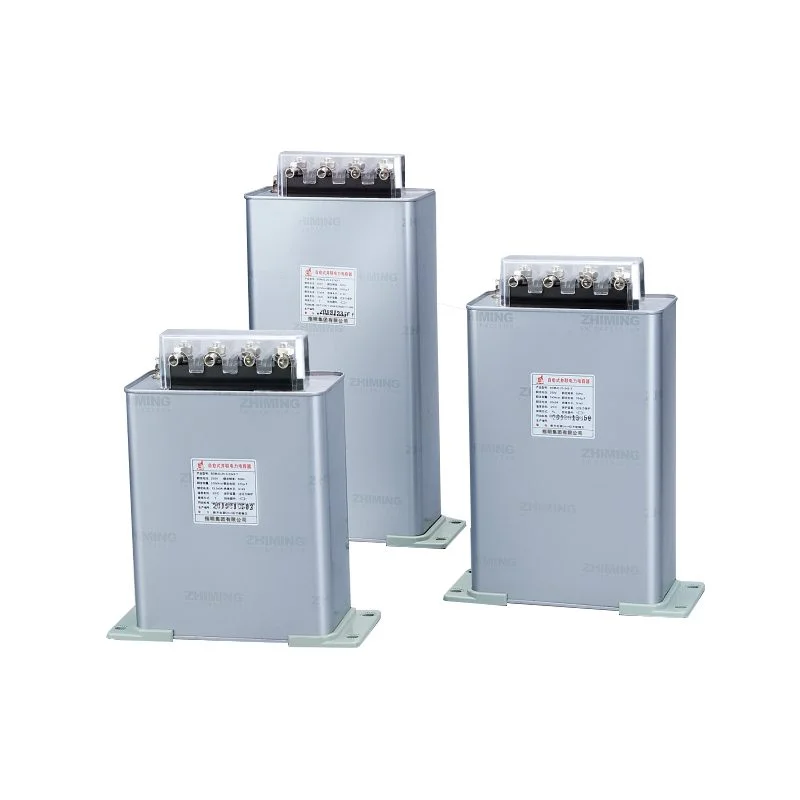
When to Use Common Compensation Reactive Power Compensation Capacitor
- The three-phase load stays roughly balanced, with no big gap in three-phase current and reactive demand;
- On-site loads are mainly three-phase motor equipment rather than scattered single-phase household or commercial appliances.
When Split Phase Reactive Power Compensation Capacitor Is Mandatory
Hybrid Reactive Power Compensation Capacitor: Common + Split Combination
Rated Voltage Selection Rules for Reactive Power Compensation Capacitor
The rated voltage parameter of a reactive power compensation capacitor directly decides its running safety and service life, and choosing the wrong voltage grade for a reactive power compensation capacitor will lead to overheating, internal aging and even breakdown failure under normal grid fluctuation. There is a unified calculation rule and site selection habit for configuring the voltage of a reactive power compensation capacitor in low voltage distribution systems.
Core Calculation Formula for Reactive Power Compensation Capacitor Voltage
Engineering designers follow a fixed formula to confirm the required rated voltage of a reactive power compensation capacitor:
Capacitor rated voltage = System nominal voltage / (1 – reactance rate)
This formula fully considers basic grid voltage level and voltage rise caused by series reactors, ensuring the selected reactive power compensation capacitor will never run under persistent overvoltage conditions.
Standard & Regional Voltage Grade for Reactive Power Compensation Capacitor
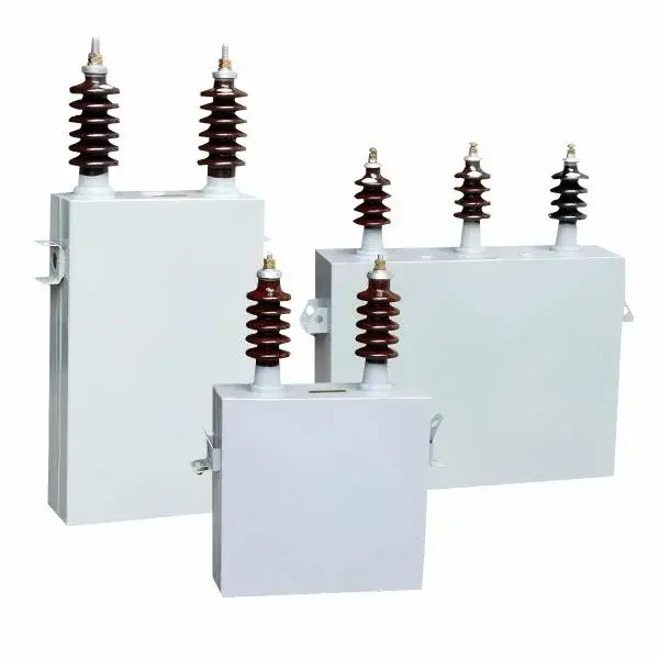
Capacity Calculation & Matching for Reactive Power Compensation Capacitor
Calculating the total required capacity is the core link before purchasing a reactive power compensation capacitor, and inaccurate capacity matching of a reactive power compensation capacitor will result in either under-compensation that fails power factor assessment or over-compensation that pushes grid voltage abnormally high. Three mature calculation methods are widely used to confirm the total capacity of the reactive power compensation capacitor for different project stages.
Maximum Load Calculation (Most Accurate for Reactive Power Compensation Capacitor)
| Initial Power Factor | Target 0.90 | Target 0.92 | Target 0.95 | Target 1.00 |
|---|---|---|---|---|
| 0.60 | 1.00 | 1.06 | 1.13 | 1.33 |
| 0.75 | 0.58 | 0.64 | 0.71 | 0.91 |
| 0.80 | 0.42 | 0.48 | 0.55 | 0.75 |
| 0.85 | 0.20 | 0.26 | 0.33 | 0.53 |
Take a real case: a factory max active load hits 500kW, initial power factor 0.80, target 0.95. Check the table to get K=0.55, total required reactive power compensation capacitor capacity = 275kvar, so the site needs to assemble a reactive power compensation capacitor combination reaching 275kvar in total.
Transformer Capacity Estimation for Reactive Power Compensation Capacitor
In early project design when real load data is unavailable, the total size of the reactive power compensation capacitor can be roughly estimated by transformer capacity, with a common empirical range of 20% to 40% of transformer kVA rating.
Formula: Qc = (20% ~ 40%) × S
For a 1000kVA transformer, taking 30% as the middle value, the matched reactive power compensation capacitor capacity is 300kvar. It must be noted this is only a rough budget reference, and the final reactive power compensation capacitor configuration needs precise recalculation after the system runs normally.
Electricity Bill Penalty Reverse Calculation for Reactive Power Compensation Capacitor
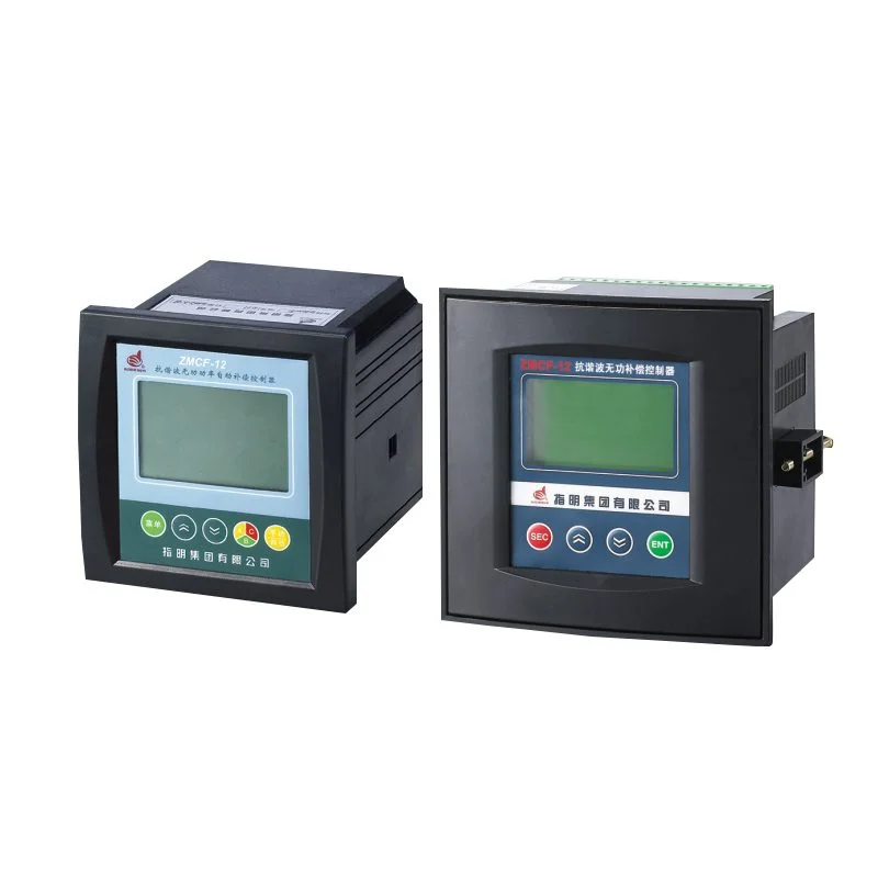
When power suppliers issue power factor penalty notices, the document clearly marks the actual operating power factor. Engineers can use this value as the initial cosφ1, set the target to 0.90 or 0.92 to avoid further fines, then apply the maximum load formula to calculate the exact reactive power compensation capacitor capacity needed for renovation, and configure a suitable regulator kompensacji mocy biernej for automatic operation. This method is highly practical for old plant grid upgrading and reactive power compensation capacitor replacement projects, and the matched reactive power compensation controller ensures stable real-time power factor regulation after renovation.
Single Unit Step & Capacity Matching of Reactive Power Compensation Capacitor
- Adopt gradient mixed specifications instead of identical single-unit reactive power compensation capacitor; flexible combination input avoids obvious over or under compensation.
- Sites with violent load fluctuation such as welding workshops need a small step size reactive power compensation capacitor to capture rapid reactive changes.
- The largest single reactive power compensation capacitor should not exceed 1/10 to 1/5 of total capacity, preventing big switching impact on the grid.
Key Factors Affecting Reactive Power Compensation Capacitor Capacity
Reactance Rate Matching for Reactive Power Compensation Capacitor & Reactor
In grids with harmonic pollution, every reactive power compensation capacitor must be matched with a harmonic filter reactor, and proper reactance rate selection is critical to protect the reactive power compensation capacitor and suppress harmonic interference. Wrong reactance rate will trigger grid resonance, amplify harmonic current, and burn out the reactive power compensation capacitor in a short time.
Reactance Rate & Dominant Harmonic Matching for Reactive Power Compensation Capacitor
- 3rd harmonic dominated sites: Choose 12%~14% reactance rate, suitable for commercial buildings and data centers with heavy single-phase loads that easily damage the reactive power compensation capacitor.
- 5th harmonic dominated sites: Choose 5%~7% reactance rate, the most common match for industrial sites with frequency converters, best protecting the reactive power compensation capacitor from mainstream industrial harmonics.
- 7th harmonic dominated sites: Choose 3% reactance rate, only used when 7th harmonic is far higher than other components.
Judging On-site Harmonics to Protect Reactive Power Compensation Capacitor
- Empirical judgment: Mass use of frequency converters and switching power supplies means 5th harmonic leads, 7% reactance rate is the safest default choice for the reactive power compensation capacitor.
- Instrument testing: Use power quality analyzers to get harmonic spectrum data, then select the exact reactance rate to perfectly coordinate with the reactive power compensation capacitor.
Resonance Avoidance to Safeguard Reactive Power Compensation Capacitor
Mismatched tuning frequency will cause parallel resonance between reactor and reactive power compensation capacitor, magnifying voltage and current stress on the reactive power compensation capacitor and leading to bulge, leakage or breakdown. The widely used 7% reactance rate sets the tuning frequency between 3rd and 5th harmonic, effectively avoiding resonance points and creating a stable working environment for the reactive power compensation capacitor.
FAQ
Does every industrial site need a hybrid reactive power compensation capacitor?
Not at all. Sites purely with balanced three-phase motors and stable loads can use only a common reactive power compensation capacitor to save cost. Only when single-phase unbalanced loads mix in the workshop will a hybrid reactive power compensation capacitor be necessary to balance each phase and stabilize the running state of the reactive power compensation capacitor system.
Why cannot standard 400V reactive power compensation capacitor be used in Vietnam?
Vietnam’s grid has larger voltage swings and heavier harmonics than regular domestic systems. A conventional 400V or 415V reactive power compensation capacitor lacks enough voltage margin, running under long-term overvoltage and aging quickly. A 450V grade reactive power compensation capacitor fits the local harsh grid well and prolongs the service life of the whole reactive power compensation capacitor set.
What risks come with wrong reactance rate for reactive power compensation capacitor?
Improper reactance rate fails to suppress harmonics first, making the reactive power compensation capacitor work under distorted voltage continuously. Worse still, it induces resonance, amplifies harmonic impact, causes overheating and breakdown of the reactive power compensation capacitor, and even affects the normal operation of the whole plant power distribution system.