Modern electrical grids are complex ecosystems. Every day, large industrial motors, massive HVAC systems, and thousands of transformers pull energy from the grid. However, these inductive loads do not just consume active power—they also demand reactive power to sustain their magnetic fields. This unseen demand creates significant drag on the system, dropping efficiency and causing voltage drops. To solve this, electrical engineers rely on the power capacitor. Acting as localized reactive power generators, these units counteract inductive lag, stabilize voltage lines, and drastically reduce transmission losses.
Daftar Isi
What is a Power Capacitor and Why Does Modern Grid Infrastructure Need It?
At its core, a power capacitor is a passive device designed to store and release electrical energy within an alternating current (AC) network. When an electrical system contains too many inductive loads, the current lags behind the voltage. This discrepancy lowers the power factor, which represents the ratio of real working power to the total apparent power supplied to the system. A low power factor means the utility provider must supply more total current than is actually doing useful work, placing an unnecessary burden on generators, transformers, and transmission cables.
By installing a power capacitor, engineers introduce a leading current into the system. This leading current cancels out the lagging current of the motors and transformers. The practical benefits are immediate:
Reduced Line Losses: Lower total current means less heat generation and lower energy losses in the conductors.
Voltage Stabilization: Minimizing reactive current drop prevents sudden brownouts and voltage sags under heavy loads.
Capacity Optimization: Relieving transformers of reactive current demands frees up thermal capacity to handle actual load growth.
Without these static compensators scattered throughout transmission and distribution networks, modern industrial grids would suffer from systemic inefficiencies, frequent equipment overheating, and localized voltage collapse.
Categorizing Capacitors by Voltage Levels: Selection and Real-World Scenarios
Electrical networks are stratified by voltage levels, and the insulation, construction, and protection mechanisms of a capacitor must match its specific operational environment. Navigating these requirements demands a clear distinction between high and low voltage applications.
Medium to High Voltage Grid Applications
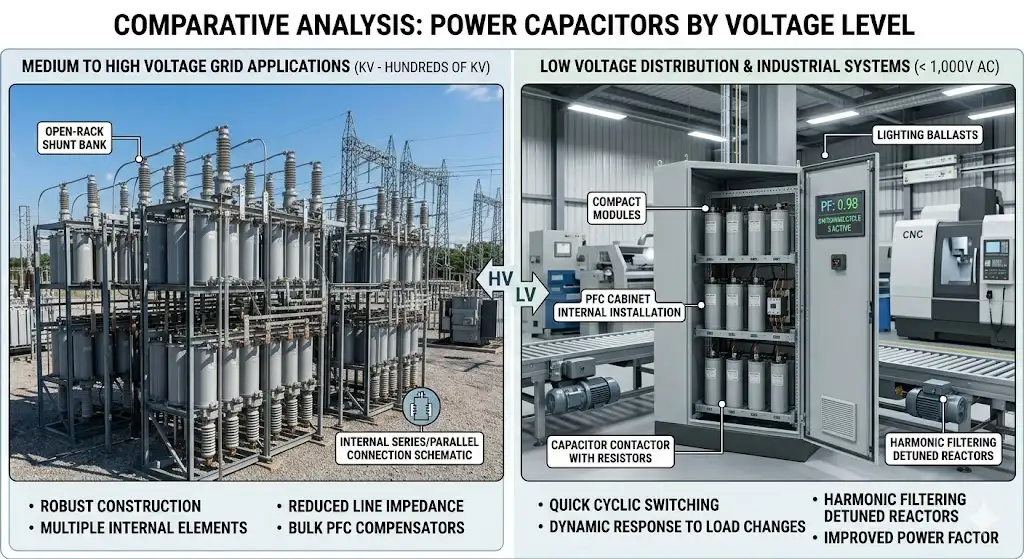
In high-voltage transmission networks and utility substations, reactive power management occurs at massive scales. These environments deal with voltages ranging from several kilovolts up to hundreds of kilovolts.
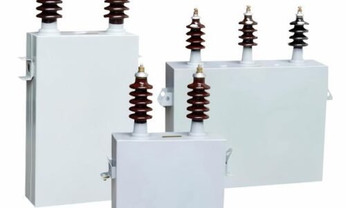
To manage power quality at this level, utilities deploy the kapasitor daya tegangan tinggi. These robust units are typically constructed using multiple internal capacitor elements connected in series and parallel groups to withstand extreme dielectric stress. They are often arranged in large open-rack shunt banks inside substations or installed in series along long-distance transmission lines to reduce inductive impedance.
Low Voltage Distribution and Industrial Systems
Further down the supply chain, commercial buildings, manufacturing plants, and small-scale workshops operate on lower voltage levels—typically below 1,000V AC. Here, the inductive load from thousands of smaller devices (like conveyor belt motors, lighting ballasts, and CNC machines) aggregates into a seriously degraded power factor.
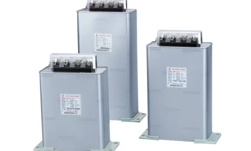
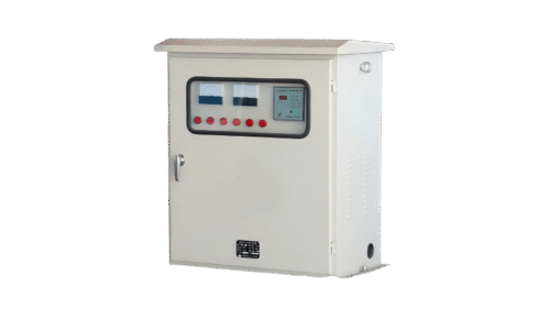
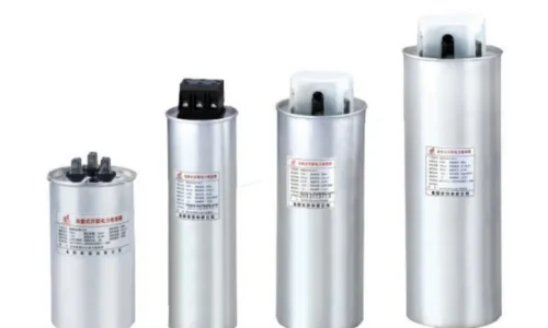
In these localized environments, the kapasitor daya tegangan rendah is the standard solution. These compact, often cylindrical or rectangular modular units are housed directly within power factor correction (PFC) cabinets. They are designed for quick cyclic switching, responding dynamically as factory machinery turns on and off throughout a standard workday shift.
Major Types of Power Capacitors Based on Construction and Dielectric Material
Beyond voltage ratings, the physical construction and the insulating material (dielectric) inside the unit dictate how a capacitor behaves under thermal stress, harmonic distortion, and overvoltage transients.
Metalized Film Capacitors
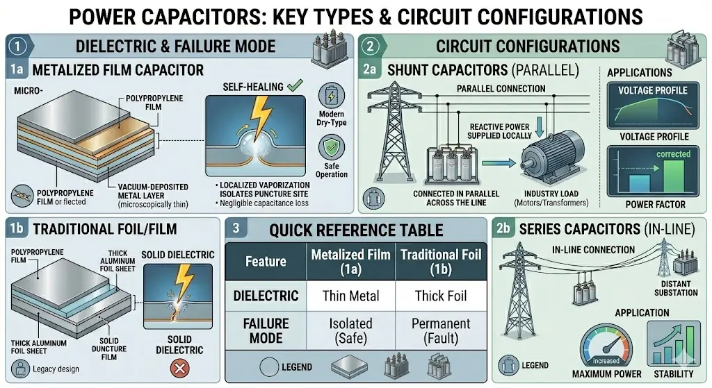
The vast majority of modern dry-type power capacitors utilize metalized polypropylene film as the dielectric material. Instead of using thick aluminum foil sheets, a microscopically thin layer of metal is vacuum-deposited directly onto the polymer film.
The standout feature of this design is its self-healing property. If an electrical surge punctures the dielectric film, the intense localized heat instantly vaporizes the thin metal layer around the puncture site. This removes the short circuit, isolates the damaged point, and allows the capacitor to continue operating safely with only a negligible loss of overall capacitance.
Shunt vs. Series Capacitors
Capacitors are integrated into electrical circuits in two distinct structural configurations, each serving a fundamentally different operational purpose:
Shunt Capacitors: Connected in parallel across the line. Their primary job is to supply the reactive power required by inductive loads locally, thereby increasing the power factor and raising the voltage profile of the surrounding network.
Series Capacitors: Inserted directly in series with transmission line conductors. Their primary job is to physically offset the inductive reactance of very long transmission lines. By reducing the total line impedance, they increase the maximum power transfer capability of the line and improve transient stability across long distances.Technical Comparison of Capacitor Types
Technical Comparison of Capacitor Types
| Feature / Metric | High-Voltage Shunt Capacitors | Low-Voltage Metalized Film | Series Compensation Capacitors |
|---|---|---|---|
| Typical Voltage Range | 1 kV to 500 kV+ | 230 V to 1000 V | 69 kV to 765 kV |
| Primary Dielectric | Polypropylene film / All-film | Metalized Polypropylene | Film / Foil matrix with fluid |
| Fungsi Inti | Substation bulk PF correction | Localized commercial/industrial PFC | Transmission line impedance reduction |
| Self-Healing Capability | No (Relies on internal fuses) | Yes (Excellent localized clearing) | No (Requires external bypass systems) |
| Average Lifespan | 15–20 Years | 8–12 Years (Load dependent) | 20–25 Years |
Crucial Switching and Control Components: Ensuring System Longevity
A power capacitor cannot simply be wired permanently to a volatile industrial busbar without a controlled mechanism to turn it on and off. The act of switching a capacitor carries severe electrical risks that must be carefully managed.
The Vital Role of Specialized Contactors
When an uncharged capacitor is connected to an AC voltage source, it acts momentarily as a literal short circuit. This causes an instantaneous rush of electrical energy known as inrush current. This inrush current can spike to over a hundred times the nominal rated current of the capacitor, lasting only a few milliseconds but causing massive voltage transients, pitting contact materials, and degrading the capacitor’s internal dielectric layers.
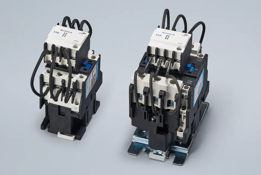
Standard magnetic AC contactors are ill-equipped to handle these intense spikes; their contacts would quickly weld together. This is why automated power factor correction systems rely on a dedicated kontaktor kapasitor.
These specialized components feature an innovative two-stage switching mechanism:
Stage 1 (Pre-charging): Early-make auxiliary contacts close first, forcing the initial current rush through a series of heavy-duty damping resistors. This safely dampens and limits the peak inrush current.
Stage 2 (Main Conduction): Milliseconds later, the main contacts close fully, establishing a direct, low-resistance path for continuous operation while bypassing the damping resistors entirely.
This dual-stage engagement shields the electrical network from voltage notches and extends the operating lifespan of both the switching gear and the capacitor banks.
Industrial and Utility Applications: Translating Theory into Efficiency
In practical application, power capacitors are rarely deployed as isolated components. Instead, they are engineered into integrated systems tailored to specific operating challenges.
Heavy Manufacturing and Steel Mills
Industrial plants operating massive electric arc furnaces, stamping presses, or heavy-duty induction motors experience volatile, fast-cycling inductive loads. In these settings, uncompensated power factors frequently dip to inefficient levels, prompting heavy financial penalties from utility providers.
Engineers deploy multi-step automatic low-voltage capacitor banks managed by intelligent microcontrollers. These controllers constantly monitor line current phase angles and step individual capacitor blocks in or out using dedicated contactors to maintain an optimal target power factor close to unity.
The Challenge of Harmonics
Modern industrial sites are flooded with non-linear loads, such as Variable Frequency Drives (VFDs), LED drivers, and server power supplies. These devices introduce harmonic distortion into the current wave, altering the standard electrical sine wave.
Because a capacitor’s internal resistance to current drops significantly at higher frequencies, high-frequency harmonic currents naturally rush into the capacitor. This causes severe thermal stress and threatens to trigger a condition known as harmonic resonance, which can destroy equipment. To prevent this, power capacitors in industrial environments are regularly paired in series with detuned reactors (inductors). These reactors are precisely sized to block high-frequency harmonics while letting the fundamental power frequency pass through to be corrected by the capacitor.
Summary: Optimizing Efficiency with the Right Power Capacitor Setup
Managing power quality is an essential part of running an efficient electrical network. Selecting and deploying the right power capacitor is not a one-size-fits-all task; it requires balancing voltage demands, environmental conditions, and systemic harmonic risks. Whether deploying a robust high voltage power capacitor to stabilize utility transmission lines, or utilizing a flexible low voltage power capacitor managed by a specialized capacitor contactor to avoid factory penalties, these components are foundational to modern energy conservation. By reducing unnecessary line current, lowering thermal losses, and reclaiming transformer capacity, power capacitors ensure that electrical systems operate reliably, efficiently, and at peak performance.
PERTANYAAN YANG SERING DIAJUKAN
How does a power capacitor improve the power factor in an inductive load environment?
In an inductive environment (dominated by components like motors and transformers), the magnetic fields cause the alternating current to lag behind the voltage, creating useless reactive power draw. A power capacitor operates with the exact opposite phase relationship, introducing a leading current. When installed, the leading current of the capacitor compensates for the lagging current of the inductive loads, bringing the total voltage and current waves back into alignment, which maximizes active working power.
What causes a high voltage power capacitor to degrade over time?
High voltage units suffer gradual degradation due to a combination of continuous dielectric stress, ambient thermal cycling, and system overvoltage transients. High voltage environments can cause micro-partial discharges within the internal insulation layers. Over time, these tiny electrical stresses carbonize the dielectric materials, slowly eroding total capacitance until internal protection fuses trigger or the unit requires replacement.
What causes a high voltage power capacitor to degrade over time?
Standard AC contactors close their contacts directly without any current-limiting middle steps. Because an empty power capacitor draws an immense, near-instantaneous inrush current spike upon connection, standard contacts will quickly pit, erode, or weld shut under the thermal shock. A dedicated capacitor contactor uses specialized early-make auxiliary contacts wrapped with pre-charging resistors to safely dampen this inrush current before the main contacts close, protecting the circuit.