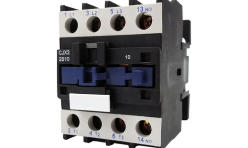
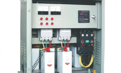
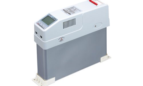
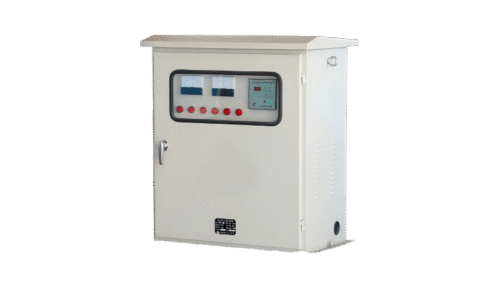
Maintaining electrical efficiency in modern industrial plants is a continuous battle against inductive loads. At the heart of this struggle is the Automatic Power Factor Controller, a sophisticated piece of industrial automation designed to keep your power factor as close to unity (1.00) as possible. When functioning correctly, this device acts as an intelligent reakti̇f güç kompanzasyon kontrolörü, constantly measuring lagging currents and engaging compensation steps to protect your system from steep utility penalties.
Understanding what goes wrong inside the controller—and the wider compensation system—is the first step toward keeping your plant running smoothly. Let us break down the ten most common issues plaguing these controllers, why they happen, and exactly how you can fix them on the plant floor.
İçindekiler
Top 10 Common Problems with Automatic Power Factor Controllers
1. Hunting and Frequent Switching of Capacitor Banks
One of the most physically exhausting failures to observe in an electrical room is “hunting.” This occurs when the controller rapidly switches a specific capacitor step on, realizes it has overcompensated, switches it right back off, notices the power factor has dropped, and turns it back on again. You will hear the rhythmic, loud clunk-clunk of contactors cycling every few seconds.
This constant cycling rapidly wears out mechanical contacts, overheats the internal discharge resistors of your capacitors, and injects severe voltage transients into your local grid. According to standards established by the International Electrotechnical Commission (IEC), rapid restriking of capacitive currents induces severe overvoltage conditions that degrade insulation over time.
The Root Cause
Hunting is almost always caused by a poorly configured C/K value or an inappropriately short dead time (delay time). The C/K value is the ratio between the capacity of the first step capacitor (C) and the current transformer ratio (K). It defines the threshold of reactive power required before the controller decides to act. If this threshold is set lower than the physical kVAR size of your smallest capacitor step, the controller enters a mathematical infinite loop: adding the step pushes the system into a leading state, and removing it drops it back into a lagging state.
The Fix
Recalculate and Re-enter the C/K Ratio: Most modern controllers feature an auto-C/K setup, but background electrical noise can confuse it. Look up your actual Current Transformer (CT) ratio (e.g.1000/5A = 200) and the kVAR rating of your smallest step, then manually input the calculated C/K value from the manufacturer’s look-up table.
Increase the Delay Time: Set the switching delay to at least 45 to 60 seconds. This gives the capacitors sufficient time to safely discharge through their internal resistors before they are eligible to be re-energized, while giving the controller a chance to average out brief load spikes.
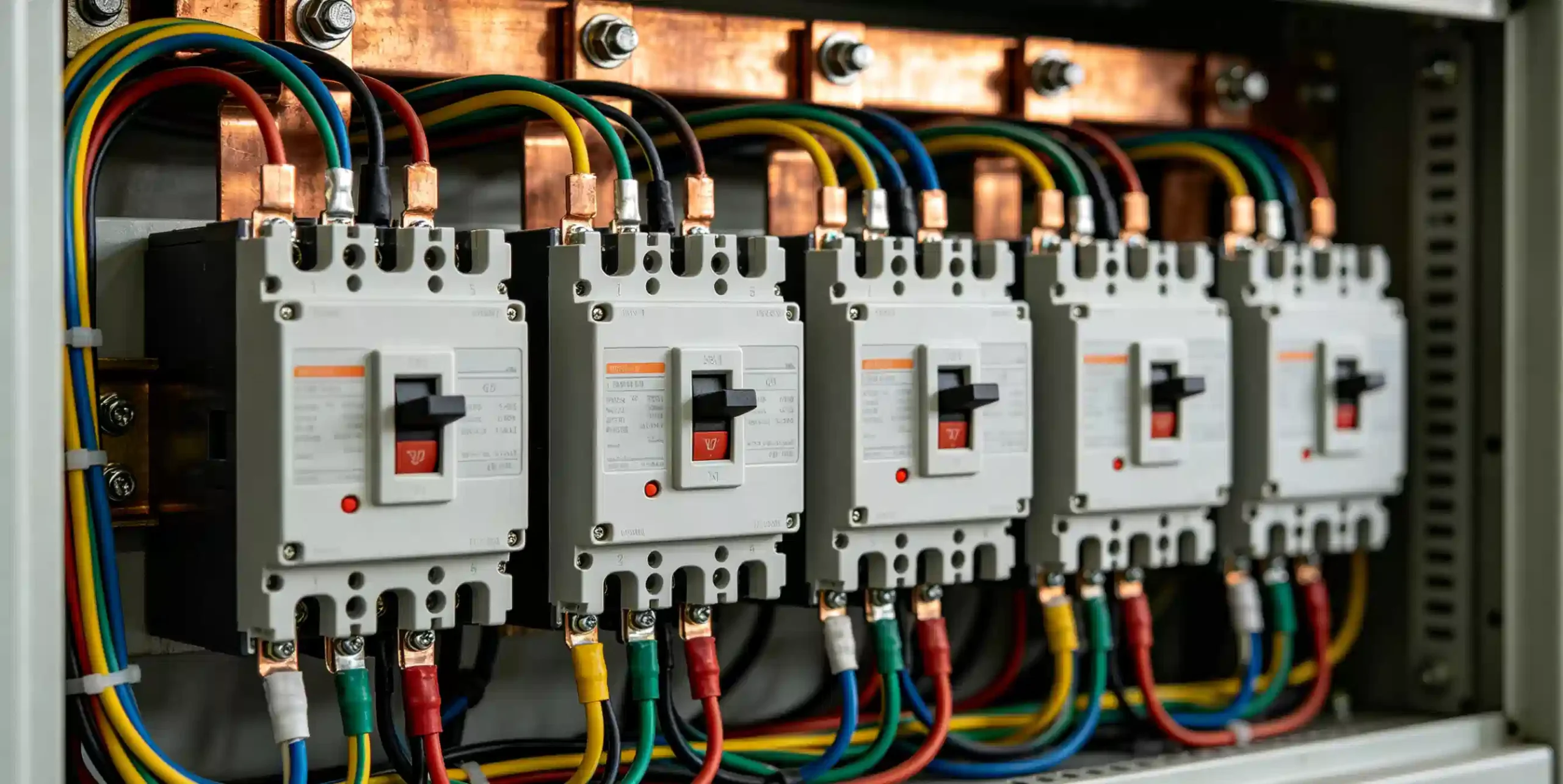
2. Incorrect Power Factor Readings on the Display
It is incredibly frustrating to look at your controller’s LCD screen, see a comforting, steady reading of 0.98 lagging, and then receive a utility bill at the end of the month penalizing your facility for an average power factor of 0.82. The controller is clearly living in an alternate reality.
The Root Cause
This disconnect typically boils down to a mismatch in the Current Transformer (CT) ratio settings inside the controller programming, or a fundamental error in where the physical CT was clamped during installation. If the CT is clamped on a busbar segment after the capacitor bank feed rather than before it, the controller cannot see the corrective kVAR it is injecting. It is essentially blind to its own actions, reading an uncompensated downstream value or a completely unrepresentative branch current.
The Fix
Verify that the main sampling CT is installed upstream of both the plant loads ve the capacitor bank connections. It must read the total combined current coming from the utility meter.
Access the factory configuration menu and check the programmed CT primary and secondary values. If you are using a 1500/5A CT, ensure the controller is not still set to its factory default of 500/5A.
3. CT Phase Reversal and Voltage-Current Mismatch
During commissioning or after a plant shutdown maintenance window, a newly restarted controller might display a highly anomalous or negative power factor (such as -0.05 or a flashing error code like Err 03 or Phase Error). The system refuses to activate any steps, leaving your plant entirely uncompensated.
The Root Cause
An automatic power factor controller requires a clear phase relationship reference to calculate the true cosine of the angle between voltage and current. If the two signal wires coming from the sampling CT (S1 ve S2) are swapped at the back terminal block, the controller perceives the current as flowing in reverse, interpreting your facility as a generator exporting active power. Alternatively, if the controller takes its voltage reference from Phase A, but the sampling CT is clamped around Phase B or Phase C without adjusting the internal phase offset software setting, the geometric math breaks down completely.
The Fix
Shut down the main breaker feeding the panel cabinet to ensure safety.
Swap the S1 ve S2 terminal connections on the back of the controller to correct physical polarity.
If the wiring is correct but the phases are mixed, use a multimeter to ensure that the phase supplying the voltage terminal matches the physical phase wrapped by the CT, or adjust the controller’s internal phase angle offset parameter (typically selectable between 0°, 90°, 180°, or 270°).
4. Overcompensation and Leading Power Factor
While a lagging power factor is the standard enemy, a leading power factor (where the current wave leads the voltage wave, often displayed with a negative sign or an explicit ‘Lead’ indicator) is equally hazardous. Overcompensation causes local busbar voltage to swell, putting immense stress on electronic equipment, variable speed drives, and lighting ballasts.
The Root Cause
Overcompensation happens when the target power factor parameter is set unrealistically high (like a strict 1.00 or a leading 0.99), or when fixed, non-switched capacitor steps have been added to the system without the controller’s knowledge. Additionally, if the output relay contacts inside the controller have physically welded shut due to a past overcurrent event, that specific capacitor bank will remain permanently energized even if the controller’s processor tries to turn it off.
The Fix
Change your target power factor setting to a more realistic 0.95 to 0.97 lagging. This leaves a safe operating buffer.
Inspect the panel for any “fixed” capacitor banks that are hardwired across the mains. If light-load conditions occur (e.g., during night shifts or weekends), these must be disconnected or brought under automated control.
Measure the voltage on the output side of the controller relays when the controller indicates that all stages should be off. If 230V or 110V control signals persist on a channel, replace the damaged controller relay or the controller entirely.
5. Failure to Respond (Under-compensation) Despite Low Power Factor
In this scenario, your plant is running heavy motor loads, the display correctly indicates a poor power factor of 0.75 lagging, but the controller sits completely inert. No step indicators light up, no relays click, and your energy efficiency remains compromised.
The Root Cause
This total lack of response usually points to a broken or un-energized control circuit loop, a blown control fuse, or an active software lockout state. Most modern micro-processing controllers feature built-in protective thresholds for undervoltage, overvoltage, and total harmonic distortion (THD). If the incoming voltage drops below a certain safety limit, or if harmonic distortion levels spike past safe boundaries, the controller will intentionally lock out all capacitor steps to protect them from exploding, sometimes without clearly displaying a plain-text warning.
The Fix
-
Use a calibrated digital multimeter to check all control fuses and miniature circuit breakers (MCBs) inside the panel cabinet. Replace any blown fuses protecting the common terminal of the output relays.
-
Look closely at the screen for small status icons or secondary menus showing parameters like %THD-V or V-rms. If the voltage is outside of the configured nominal limits (+10% -15%), you must troubleshoot the facility’s main transformer tap settings or incoming utility supply.
6. Harmonic Distortions Overloading the Controller Sensors
When non-linear loads like variable frequency drives (VFDs), heavy LED lighting arrays, and switching power supplies dominate a facility, they introduce high-frequency currents into the system. This harmonic distortion changes the clean 50 Hz or 60 Hz sine wave into a jagged, distorted mess. A standard controller can easily become overwhelmed by this noise.
The Root Cause
Older or lower-end controllers use simple zero-crossing detection algorithms to calculate the time difference between voltage and current waves. Harmonic noise creates multiple “false” zero crossings within a single cycle, confusing the microprocessor and leading to random resets, frozen screens, or inappropriate switching commands. Furthermore, harmonics cause high current amplification within standard capacitors due to resonance.
The Fix
Upgrade to a modern True-RMS sampling controller. True-RMS controllers digitally sample the entire waveform thousands of times per second, applying Fast Fourier Transform (FFT) algorithms to isolate the fundamental frequency from the noise.
Ensure that your capacitor stages are protected by a tuned or detuned reactor. These reactors attenuate high frequencies, preventing harmonic currents from feeding back into the controller’s sensitive measurement circuits.
7. Output Relay Contact Failure or Striking
You might notice an individual step indicator on the controller blinking rapidly, or you might hear a faint, continuous buzzing sound coming from the rear housing of the unit. Shortly after, that specific compensation step fails to activate entirely.
The Root Cause
The internal miniature relays found on an automatic power factor controller’s circuit board are typically rated for resistive loads up to 5 A or 10A. However, switching a capacitor bank creates an immense, instantaneous inrush current that can reach up to 100 times the capacitor’s nominal current rating. If standard industrial contactors are used without inrush limiters, or if the controller is wired to drive heavy coils directly without intermediate relays, those tiny internal contacts will spark, pit, and eventually weld together or burn open.
The Fix
Always ensure the controller’s output relays are driving a dedicated capacitor contactor equipped with front-mounted, early-make contacts and current-limiting damping resistors. These resistors absorb the brutal inrush energy, protecting both the main contacts and the upstream controller relays.
If a controller channel’s internal relay is permanently damaged, you can sometimes reprogram the controller to skip that specific damaged output terminal and use an unassigned “spare” output channel further down the terminal block.
8. Controller Overheating and Environmental Degradation
Industrial electrical rooms are rarely pristine, climate-controlled environments. Over time, an automatic power factor controller installed in a standard door cutout can begin exhibiting strange behavior: fading or scrambled LCD characters, random reboots, or an odor of overheated plastic.
The Root Cause
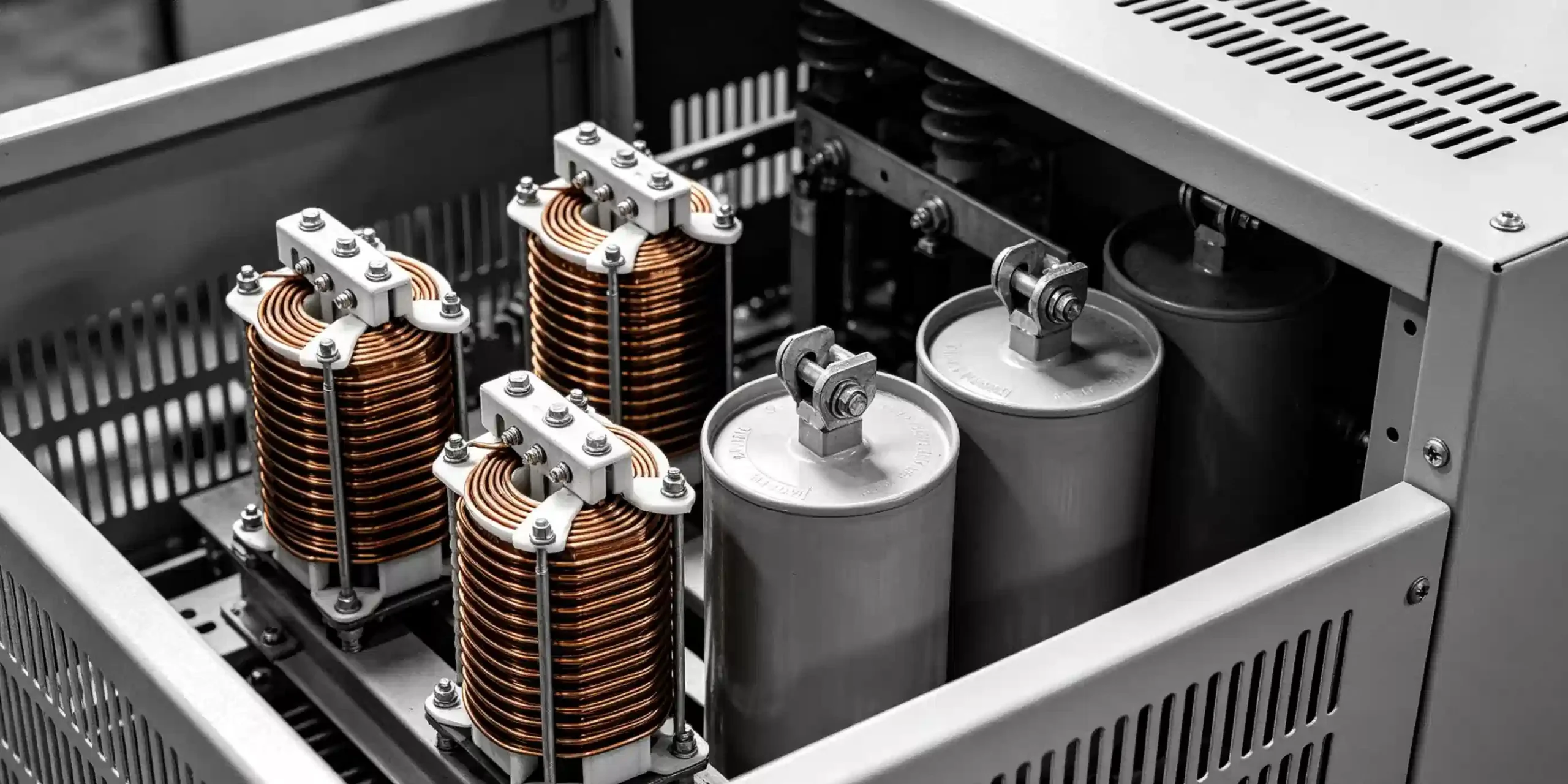
The internal components of a power factor panel generate substantial thermal energy. The power capacitor banks give off radiant heat, and if detuning reactors are installed, they act as massive thermal radiators inside the enclosure. If the panel cabinet lacks active, filtered ventilation, the internal ambient temperature can easily soar past 55℃(131℉). Prolonged exposure to high temperatures dries out the electrolytic filtering capacitors on the controller’s power supply board, causing voltage ripples that destabilize the main logic chip.
The Fix
Implement an active cooling strategy for the enclosure. Install louvers and industrial extraction fans at the top of the cabinet, with filtered intake vents near the bottom to establish an upward cooling airstream.
Use a handheld thermal imaging camera during peak plant operation to identify hot spots. Ensure that the controller chassis itself is physically isolated or shielded from the direct rising heat pathways of the reactors.
9. Faulty Auto-Calibration and Parameter Drift
Many modern controllers boast an “Intelligent Auto-Commissioning” mode. Upon initial startup, the controller sequentially steps through every output channel to learn the connected kVAR value of each capacitor bank automatically. However, this process frequently fails, throwing generic initialization error codes.
The Root Cause
Auto-calibration routines rely on a stable baseline load to accurately calculate the delta change in reactive power as each capacitor drops in. If you attempt to run auto-commissioning while the plant is experiencing highly dynamic, fast-cycling loads (such as heavy overhead cranes, robotic spot welders, or large compressors turning on and off), the controller cannot distinguish between background load fluctuations and the effect of its own capacitors. It drifts, stores incorrect values, or aborts the sequence entirely.
The Fix
Run the initialization sequence during a quiet period in the facility—such as a weekend, a planned maintenance shift, or between production runs when the background electrical load is completely static.
If the environment is naturally chaotic, bypass the automated wizard entirely. Take twenty minutes to read the physical nameplates on your capacitor steps and manually key in the exact kVAR values, step sequences, and discharge times directly into the advanced programming mode.
10. Communication Protocol and Modbus Dropping
For plants utilizing centralized Energy Management Systems (EMS) or SCADA control rooms, the controller must communicate via protocols like Modbus RTU (over RS485 wiring) or Modbus TCP/IP. A frequent issue is the sudden loss of data packets, causing the central control desk to read zero values or lose remote manual override control entirely.
The Root Cause
RS485 networks are highly susceptible to electromagnetic interference (EMI), especially when routed alongside high-voltage motor cables inside a crowded switchgear line. Missing termination resistors at the end of a long daisy-chain run cause signal reflections that corrupt data packets. Furthermore, if the baud rate, parity bit, or unique device address is misconfigured on even one instrument along the serial line, the entire communication bus can stall.
The Fix
Inspect the communication wiring. It must be a dedicated, twisted-pair shielded cable, and the shield braid should be grounded at exactly one end to prevent dangerous ground loops. Route these communication wires far away from high-power distribution cables.
Check that a standard 120 Ω termination resistor is securely installed across the A ve B communication terminals on the very last physical device in the RS485 daisy chain.
Verify through the controller’s communication menu that its slave address is unique and that its baud rate strictly matches your master PLC or SCADA gateway configuration (typically 9600 or 19200 bps).

Diagnostic Matrix: Troubleshooting at a Glance
When you are standing in front of a buzzing electrical panel with a clipboard, you need answers fast. Use this quick-reference matrix to link common physical symptoms to their underlying causes and corrective actions.
| Observed Symptom / Error | Probable Root Cause | Recommended Diagnostic Tool | Core Corrective Action |
|---|---|---|---|
| Rapid, rhythmic clunking of contactors (Hunting) | Mconfigured C/K threshold value or insufficient discharge delay time. | Stopwatch & Manufacturer Chart | Readjust C/K ratio manually; set step delay timer to ≥ 45seconds. |
| High power factor shown, but penalized by utility | Main sampling CT placed in wrong location or incorrect internal ratio. | System Single-Line Diagram | Relocate CT upstream of all loads and capacitor feeds; verify ratio settings. |
| Flashing Phase Error or Negative Power Factor | Swapped S1/S2 CT lines, or voltage reference phase mismatch. | Digital Multimeter (Phase Rotation) | Isolate power and reverse CT wire polarity; realign voltage sample phase. |
| System remains in a continuous leading state | Target power factor set too high; welded controller relay contacts. | Clamp-on Ammeter / Voltmeter | Lower target PF to 0.96 lag; check for stuck relay voltage outputs. |
| Low power factor, but controller remains idle | Blown control loop fuse or active safety lockout due to bad power quality. | Continuity Tester / Multimeter | Replace blown control circuit fuses; check voltage limits and %THD levels. |
| Erratic resets, frozen screen, ghost inputs | High-frequency harmonic distortion interfering with zero-crossing logic. | Power Quality Analyzer | Upgrade to a True-RMS sampling controller; install detuned [reactor] components. |
Best Practices for Maintaining Your Power Factor Correction System
Preventative maintenance is what ultimately keeps these automated controllers out of trouble. By treating the system as a critical asset rather than a forgotten box in the corner, you can easily double the lifespan of its internal components.
Execute Bi-Annual Thermal Audits: Every six months, open the cabinet door under full load and scan all terminal blocks, contactors, and capacitor casings with an infrared camera. High thermal profiles on a single contactor terminal indicate a loose connection that will eventually cause voltage imbalances at the controller inputs.
- Verify Current Draw per Step: Use a flexible clamp-on current meter to periodically measure the actual current drawn by each capacitor bank when forced on. If a bank’s current draw drops more than 10% below its rated nameplate value (I = kVAR/√3*V), the internal dielectric material of the güç kondansatörü has degraded, meaning the controller’s programmed step parameters no longer match reality.
Keep Enclosures Free of Conductive Dust: Carbon dust and fine metallic particulates common in industrial manufacturing environments can settle across the rear circuit boards of an automatic power factor controller. This creates micro-shorts that mimic software glitches. Use low-pressure compressed air or specialized electrical contact cleaners to clear the unit during scheduled plant shutdowns.
Sonuç
An Automatic Power Factor Controller is an invaluable tool for operational cost reduction, but its reliability is entirely dependent on the clarity of its sensory inputs and the health of its surrounding switchgear. Most failures blamed on faulty microprocessors are actually installation errors, neglected environmental conditions, or mismatched software variables.
Taking a systematic approach to diagnosing hunting, confirming phase relationships, and shielding your controller from intense harmonic environments ensures your power factor stays locked right where it belongs. This proactive maintenance protects your facility from unexpected utility surcharges and keeps your distribution gear running cool and efficient.
SSS
Can a mismatched CT ratio physically damage the automatic power factor controller over time?
A mismatched CT ratio does not directly harm the controller’s electronic hardware, because the physical current entering the terminals is safely scaled down by the transformer to a standard 1 A or 5 A maximum. Instead, the damage is entirely operational. The controller acts on incorrect mathematical representations of the grid load. This leads to issues like chronic overcompensation, which raises system voltage, or severe undercompensation, which causes prolonged heat buildup across downstream components.
How does ambient humidity inside the panel cabinet affect the controller’s microprocessors?
High humidity triggers a subtle phenomenon known as electrochemical migration. When moisture mixes with fine industrial dust on the controller’s internal circuit board, it forms conductive tracking paths. This allows low-voltage logic signals to leak between the microscopic pins of the microprocessor, leading to issues like random software resets, corrupted memory configurations, or false sensor readings that are incredibly difficult to diagnose.
Why do some intelligent controllers clear their historical log data after a minor voltage sag?
This usually points to a failing internal EEPROM (Electrically Erasable Programmable Read-Only Memory) chip or a dead lithium backup battery inside the controller chassis. When a voltage sag occurs, the main power supply rail momentarily drops below the processor’s minimum operating voltage threshold. Without a healthy internal backup battery or clean capacitor discharge buffering to sustain the memory cache during that millisecond transition, the controller performs a hard reset, wiping out temporary historical logs and reverting to its default state.