Spis treści
Why Capacitor Bank Maintenance Matters
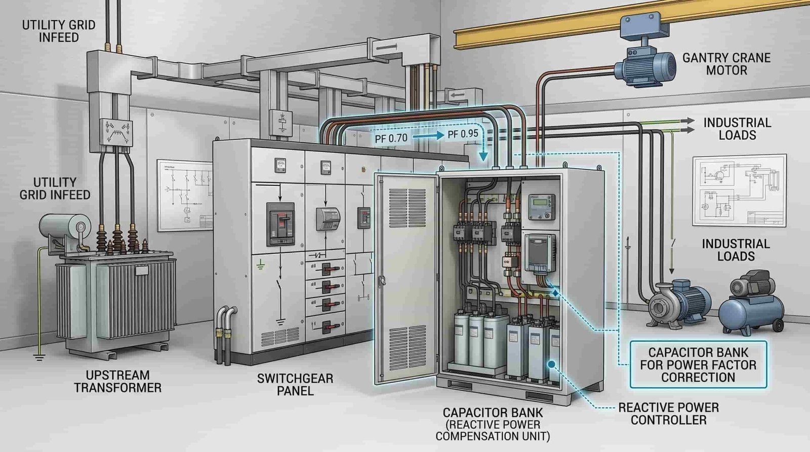
Power factor correction systems sit quietly in electrical rooms and substations, doing their job without much fanfare—until they don’t. A properly maintained capacitor bank can provide reliable reactive compensation well over ten years, but neglect tends to compound quietly. Utility power factor penalties start rising, individual units begin to overheat, and one day a catastrophic failure takes a whole section offline during a critical production window.
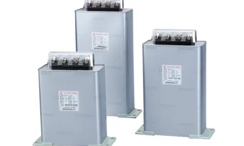
The economics are fairly simple. Most industrial units put in these systems to avoid utility surcharge and to release transformer capacity. In medium- and high-voltage substations, these systems are often built around High Voltage Power Capacitors, which require periodic inspection to maintain stable reactive power compensation performance.
When a capacitor bank goes bad, the story for the unit is one of penalties plus the cost of emergency replacement. On the other hand, the cost of preventive maintenance is just a small fraction of what downtime will reactively cost. More importantly, perhaps, is the fact that many people do not realize that the difference between preventive and predictive methods is in the implementation. The first one is by the book—check the connections every quarter, measure capacitance once a year. The second one is by the data—trace temperature trends, monitor capacitance drift, and change units before they fail, not after.
Before diving into routine procedures, understanding common failure modes can help you know what to look for during inspections. Our guide on How to Troubleshoot Bank kondensatorów covers the diagnostic side in detail.
Safety First: Pre-Maintenance Protocols
The 5-Minute Rule and Stored Energy Hazards
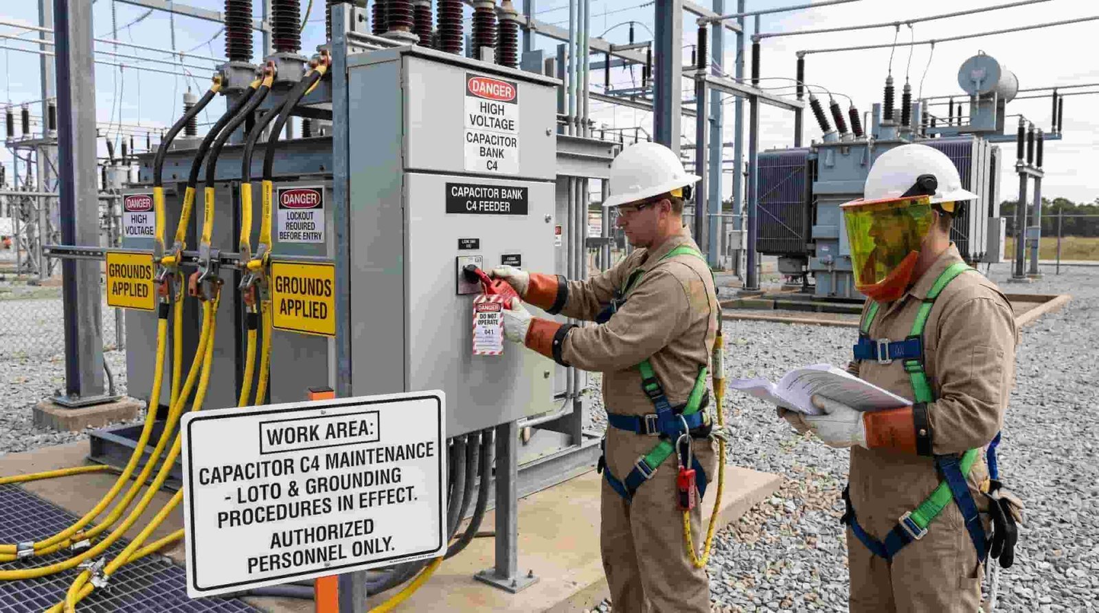
Capacitors store energy. This seems quite obvious, but it is surprising how often de-energized capacitor equipment is treated like any other disconnected load by technicians. Terminal voltage must be brought below 50 volts within 5 minutes of de-energization as per IEEE Std 18, and in fact, it really means waiting — waiting for the full 5 minutes before going near the terminals. Some larger banks may need longer, and relying on a “feels about right” timeline has led to serious injuries.
Grounding should be given equal attention. All three phases must be grounded, and the individual capacitor units must be shorted terminal-to-terminal before commencing any work. The stored energy in a large power factor correction bank is not theoretical; it can give a lethal shock even minutes after disconnection. A common mistake made by field personnel is to assume that the discharge resistors are working and, therefore, this testing is one of the routine tests included in a good maintenance program.
Personal Protective Equipment
One should be aware of the arc-flash boundary around capacitor banks. This is because the energy that would be released due to the failure of a capacitor unit or switching transient can be quite substantial. Proper PPE would include arc-rated clothing, insulated gloves at the system voltage, and face protection. Tools need to be insulated. Any work with dielectric fluid must know PCB potential in older installations. For safety’s sake, consider the oil in these banks PCB-contaminated until test results prove otherwise, if it is a pre-mid-1980s unit.
Visual Inspection: What Your Eyes Can Tell You
Monthly Walk-Through Checklist
A lot of diagnostic information is surprising in that it comes from just looking. A habit should be formed of the monthly visual inspection, and the checklist is simple:
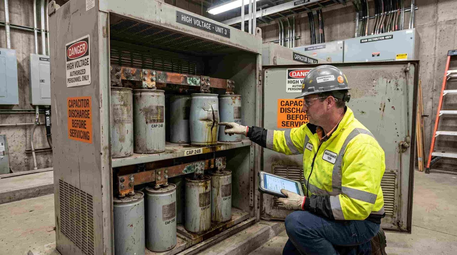
– Bulging or ruptured cans — The internal pressure from overheating or failure of the elements causes the case to deform. This is not a cosmetic; it is a failure that is in progress.
– Leaks or stains of oil — Dielectric fluid escaping indicates degradation of the seal or stress in the case. Any leaking unit should be de-energized and replaced.
– Blown fuses or damaged fuse tubes — In externally fused banks, that’s pretty obvious. In internally fused designs, the failure is hidden — making other tests more critical.
– Discoloration and burn marks — Arcing, loose connections, or prolonged heating over time leave their signatures.
– Bushings and insulators contaminated with dirt or cracked— Contamination reduces insulation integrity and encourages tracking.
– Connections and enclosures corroded— More so in coastal or chemically aggressive areas.
– Ventilation blocked and filters dirty— Banks with forced-air cooling cannot get rid of the heat if the airflow is blocked. What Different Warning Signs Mean Bulging: Mostly, this means there is gas generation inside from dielectric breakdown. Maybe the pressure relief has gone off, or maybe not — but the unit is bad. Oil leaks: Either there’s some mechanical damage to the case or years of thermal cycling have finally taken their toll on seals. Discoloration on the case or connections tells of months of slow thermal stress. Early enough to schedule a unit replacement instead of having an unplanned outage. That’s what catching these signs early means.
What Different Warning Signs Mean
Bulging typically indicates internal gas generation from dielectric breakdown. The pressure relief mechanism may or may not have activated yet, but the unit is compromised. Oil leaks suggest either mechanical damage to the case or thermal cycling that has degraded seals over years of operation. Discoloration on the case or connections often tells a story of thermal stress that has been building for months. Catching these signs early is the difference between a scheduled unit replacement and an unplanned outage.
| Warning Sign | Likely Cause | Recommended Action |
|---|---|---|
| Bulging can | Internal gas pressure from overheating or element failure | De-energize and replace immediately |
| Oil leak | Seal degradation or case stress | Replace unit; check for PCB content |
| Blown fuse | Internal element short or overcurrent event | Replace fuse; measure capacitance |
| Discoloration/burn marks | Loose connection or prolonged thermal stress | Tighten connections; thermal scan |
| Cracked bushing | Mechanical damage or material aging | Replace unit; inspect mounting |
| Blocked ventilation | Dust accumulation or debris | Clean filters; verify fan operation |
Electrical Testing: Going Beyond the Surface
Capacitance Measurement
Capacitance testing is arguably the most definitive electrical test for a capacitor unit. A digital capacitance meter connected directly to the terminals provides a direct reading. Alternatively, the current-at-known-voltage method—applying a controlled AC voltage and measuring current draw—yields the same information with basic equipment.
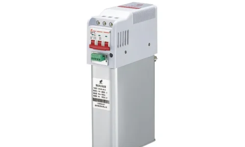
The tolerance window matters. Per IEEE Std 18, standard shunt capacitor units should read between -0% and +10% of the nameplate rating. Low-voltage units above 100 kvar have a tighter window of -5% to +5%. Regular testing is particularly important for Low Voltage Power Capacitors used in automatic power factor correction panels, where capacitance drift can directly affect compensation accuracy.
Readings outside these ranges indicate degradation. A unit measuring 15% below nominal, for example, has likely lost internal elements and is operating its remaining sections at elevated stress.
What many maintenance programs miss is the value of baseline recording. A unit reading +8% today may seem acceptable, but if it was +2% three years ago, the upward trend suggests progressive dielectric thinning. Baseline data transforms a snapshot test into a predictive tool.
Temperature also affects readings. Capacitance changes with temperature, so comparing a summer measurement to a winter baseline without correction can be misleading. Record ambient temperature alongside every measurement.
Insulation Resistance Testing
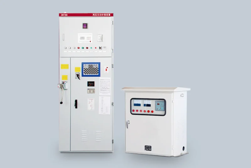
A megohmmeter test between terminals and from each terminal to case reveals moisture ingress and dielectric degradation. Declining insulation resistance values over time suggest the dielectric is breaking down, even if capacitance still reads within tolerance. For banks in humid environments or outdoor installations, this test is particularly valuable.
Voltage and Current Balance Checks
Phase-to-phase unbalance is often the first electrical indicator of trouble in a three-phase bank. A clamp meter on each phase during operation can reveal a failed element or blown fuse before it becomes critical. For banks with unbalance protection relays, verifying that the relay trips at the correct setpoint is essential. IEEE Std C37.99 provides detailed guidance on unbalance detection settings.
| Test | Częstotliwość | Key Parameter | Pass/Fail Criteria |
|---|---|---|---|
| Capacitance measurement | Annually | µF or kvar | Within -0% to +10% of nameplate |
| Insulation resistance | Annually | Megohms | >100 MΩ (varies by voltage class) |
| Voltage balance | Quarterly | Phase-to-phase voltage | <2% unbalance under normal load |
| Current balance | Quarterly | Phase current | <5% deviation from average |
| Unbalance relay test | Annually | Trip setpoint | Verify per manufacturer settings |
Thermal and Harmonic Health Monitoring
Infrared Thermography
In the maintenance of capacitor banks, thermal imaging is considered one of the most important diagnostic tests. A hot spot on a connection indicates looseness or corrosion. A hot spot on the body of the capacitor reveals mostly inside element degradation or dielectric loss. The most important requirement is that the bank should be under normal running conditions for at least an hour before it is scanned; an immediate scan after energization is cold and misses the thermal signature which builds up during steady-state operation.
Comparing thermal images from one inspection cycle to another builds a trend profile. A unit that was 5°C above ambient last year and is now 15°C above ambient — that”s a clear signal, even if electrical tests still pass.
Harmonic Distortion Assessment
Modern industrial environments are increasingly hostile to standard capacitor banks. Variable frequency drives, LED lighting, and switch-mode power supplies inject harmonic currents that can resonate with capacitor banks, amplifying distortion rather than correcting it. Measuring total harmonic distortion (THD) at the point of common coupling should be part of any comprehensive maintenance program.
If THD levels exceed IEEE 519 recommendations, simply replacing failed capacitor units will not solve the underlying problem. In these situations, a detuned reactor in series with the capacitor bank shifts the resonant frequency away from problematic harmonics. The reactor sizing—typically 5.67%, 7%, or 14% depending on the dominant harmonic order—should be determined by a proper harmonic study.
Control System and Switching Component Checks
Contactor and Switching Device Maintenance
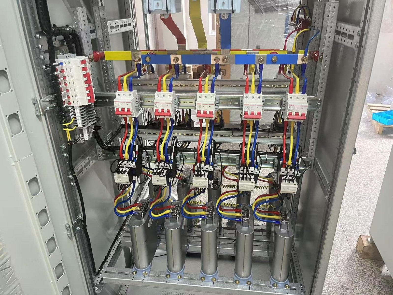
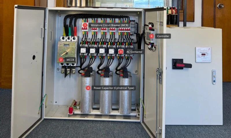
Capacitor-duty contactors are not ordinary motor contactors. They include pre-charge resistors and are designed to close at voltage zero-crossing to minimize inrush current. These components wear with every switching operation. A bank switched ten times per day accumulates over 3,600 operations annually. Contact inspection and replacement should be based on operation count, not calendar time.
Signs of contactor wear include welding, pitting, and inconsistent closing timing. The pre-charge resistors should also be checked for proper resistance value; an open resistor means the next closure will subject the capacitors to full inrush current.
Controller and Panel Display Meter Verification
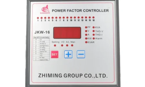
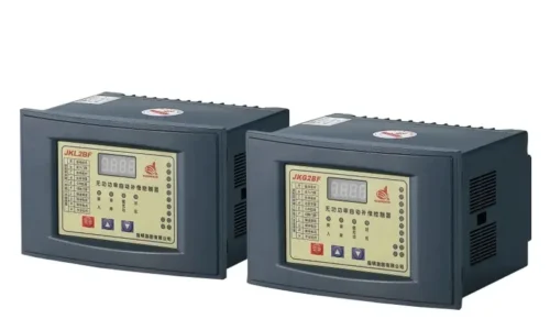
The power factor controller is the brain of an automatic capacitor bank but is often the most neglected component. Calibration drifts over time, and the settings that were good five years ago may no longer match the profile of the loads of the facility. A full calibration of the controller every three to five years is reasonable for most installations.
Indicator lights, door interlocks, and limit switches should be function-tested during each maintenance cycle. The panel display meter should be checked against a calibrated reference to ensure voltage, current, and power factor readings are accurate. Inaccurate metering leads to incorrect switching decisions and, ultimately, poor power factor performance.
A Practical Maintenance Schedule
Discipline matters more than complexity. The following schedule balances thoroughness with practicality for most industrial installations.
Facilities in harsh environments—high dust, coastal salt air, or extreme temperatures—should compress this schedule. Conversely, lightly loaded indoor banks in clean environments may tolerate slightly extended intervals, though annual electrical testing should remain non-negotiable.
Documenting and Tracking Results
Without documentation, maintenance is simply slow troubleshooting. All measurements should be documented along with the date, ambient conditions, and equipment identifier; this includes capacitance, insulation resistance, temperature, and voltage balance. Digital logs would be better since they allow for trend analysis, which paper records would not be able to support.
The actual value comes out over years. A unit with a drift in capacitance from +2% to +7% over four years is not out of tolerance yet, but the trend would indicate replacement within the next maintenance cycle. This is predictive maintenance in practice — acting on trends instead of waiting for failures.
If and when data does cross thresholds, the decision between replacement and repair is usually quite simple for individual capacitor units since in most cases, they are not field-repairable in any meaningful sense—replacement being the only practical option. For the bank as a whole, however, trend data may indicate that a cluster of units from the same manufacturing batch is degrading together, justifying a group replacement before the onset of cascading failures.
Wnioski
Routine maintenance on a capacitor bank is not particularly complex, but it does require consistency and attention to detail. The monthly visual inspection catches obvious problems before they escalate. Quarterly electrical checks maintain connection integrity and balance. Annual comprehensive testing—capacitance, insulation resistance, thermal imaging, and harmonic analysis—provides the data needed for predictive decisions.
Facilities that treat capacitor maintenance as a checkbox item tend to discover problems during outages. Those that build disciplined programs around measurement, documentation, and trend analysis typically see service lives of fifteen years or more from their power factor correction equipment. The difference is not the sophistication of the testing equipment; it is the consistency with which the basics are executed.
FAQ
Can a capacitor bank with one failed unit continue operating?
Yes, technically, especially in large banks with many parallel units. However, the remaining units absorb the reactive load that the failed unit can no longer supply. This raises their operating voltage and thermal stress. According to IEEE Std 1036, overvoltage on healthy units should not exceed 110% of rated voltage. If the loss of one unit would push the others over this limit, then the operation of the assembly should be considered to accelerate the degradation risk on the entire assembly; hence, the better way is to de-energize the affected step or group and replace the failed unit as soon as possible.
Why do some capacitor banks require detuned reactors while others don't?
It depends entirely on the harmonic environment of the electrical system in question. A site with minimal nonlinear load—say basic induction motors and resistive heating—can often run standard capacitor banks with no problems. Once variable frequency drives, large UPS systems, or extensive LED lighting come into play, harmonic currents set the stage for resonance. A detuned reactor simply moves the resonant frequency of the capacitor bank below the fifth harmonic so that there is no amplification. A reactor should be decided by a harmonic analysis, not assumed.
How does altitude or ambient temperature affect maintenance intervals?
Both of these factors put more severe stress on capacitor dielectrics as compared to standard conditions. At higher altitudes, the reduced density of air hampers the dissipation of heat from air-cooled units. Ambient temperatures above the rated 40°C or 45°C limit will hasten the aging of insulation. Facilities at altitude or in hot climates should, therefore, check thermal performance more often and probably consider derating the bank’s output. The nameplate kvar rating assumes standard conditions; real output in a 55°C room will be lower, and the units will run hotter, shortening effective lifespan.