Choosing an automatic power factor controller sounds fairly straightforward at first glance. In practice, it rarely is. Electrical systems behave differently from site to site, loads change in ways that can be hard to predict, and the “best” controller on paper is not always the one that performs best once installed. That is usually where the real decision-making begins.
For facilities trying to reduce wasted energy, stabilize voltage behavior, and avoid penalties tied to poor power factor, the controller becomes more than a small accessory in the cabinet. It ends up shaping how smoothly the whole compensation system works. And while the market is full of similar-looking products, the differences often show up in response speed, step logic, reliability, and how well the controller handles the messy reality of modern loads.
Spis treści
What an Automatic Power Factor Controller Actually Does
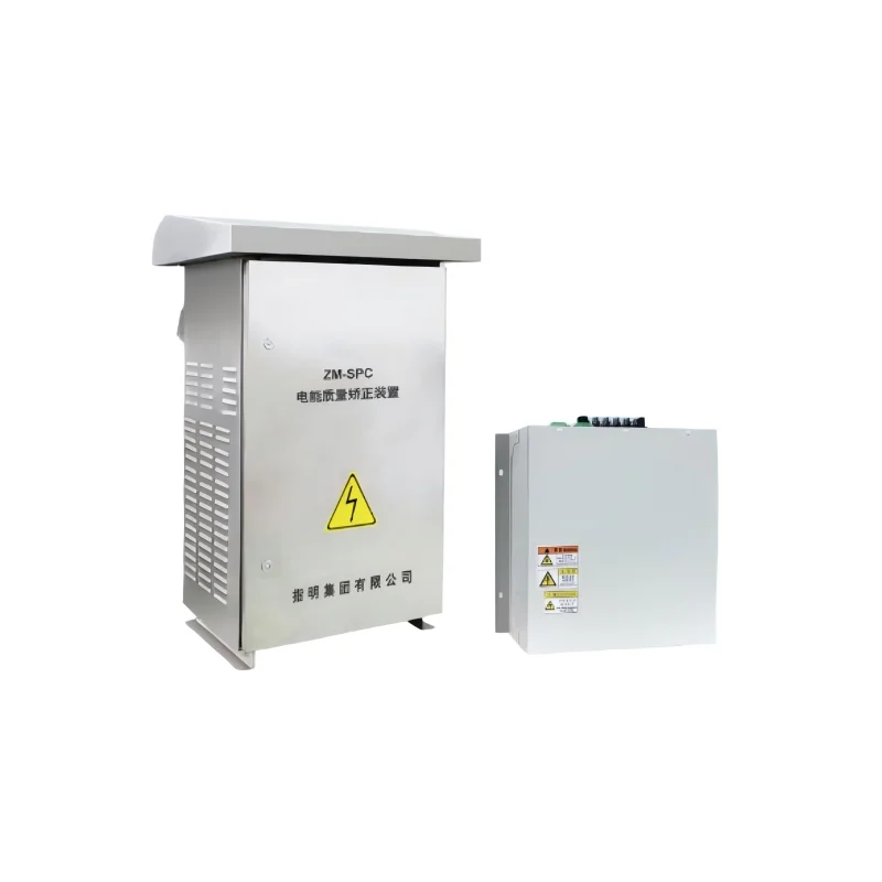
An Automatic Power Factor Controller monitors the power factor of an electrical system and switches capacitor steps in or out as needed to keep it close to a target value. That may sound simple, but the job is fairly sensitive. If the controller reacts too slowly, compensation lags behind demand. If it reacts too aggressively, the system can overcompensate, which is just another problem wearing a different name.
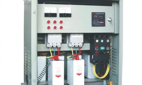
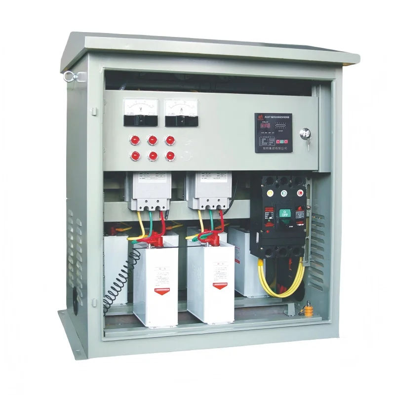
In most installations, the controller works with a current transformer and capacitor bank, measuring reactive demand and deciding when each step should be connected. The goal is not perfection in a textbook sense; it is stability, efficiency, and avoiding unnecessary switching. A well-tuned system can reduce line losses, improve transformer utilization, and keep the electrical network more balanced.
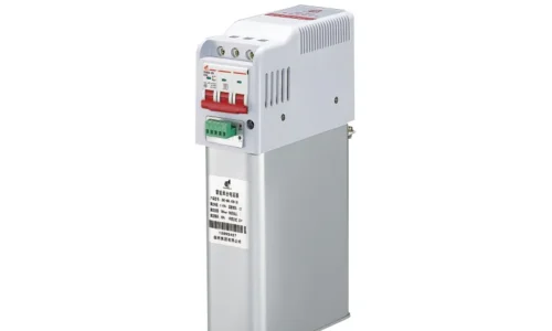
For a closer look at a typical solution, the product page for this Automatic Power Factor Controller gives a useful sense of the features many buyers compare first.
Why Selecting the Right Controller Matters More Than People Think
People sometimes assume power factor correction is mostly about choosing the right capacitor size. That is only part of the story. The controller determines how intelligently those capacitors are used. If it makes poor decisions, the whole compensation system can become inefficient even if the hardware itself is good.
There are a few common issues that show up when the controller is a mismatch for the site:
- Frequent hunting between capacitor stages
- Delayed compensation during load swings
- Unnecessary wear on contactors and capacitors
- Overcorrection at low load
- Energy savings that look good on paper but feel disappointing in real operation
Facilities with stable, predictable loads can tolerate a simpler control approach. But plants with variable machinery, intermittent motors, welders, compressors, or mixed industrial loads usually need more responsive logic. This is where the differences between controllers become noticeable.A broader regulator kompensacji mocy biernej setup can also help frame the selection process, especially when the controller is only one part of a larger compensation strategy.
Key Factors to Evaluate Before Buying
Load type and variation
This is usually the first thing to assess, even if it gets skipped in practice. A facility with steady base loads behaves very differently from one with fast-changing demand. Some controllers handle gradual changes well but struggle when the load jumps around. Others are designed for quicker switching and more adaptive behavior.
The rough question is simple: does the system need calm, steady correction, or rapid response to frequent changes?
Number of steps and switching strategy
The number of capacitor steps affects how finely the controller can match compensation to demand. More steps often means better accuracy, but only up to a point. Too many steps can add complexity without much practical benefit.
A balanced setup usually depends on:
- The size of the load
- How often demand changes
- How sensitive the process is to reactive swings
- Whether the capacitor bank is designed for fine-grained correction or broader blocks
In many systems, moderate step granularity works better than maximum complexity.
Measurement accuracy and response speed
These two qualities are closely related, even though they are often discussed separately. If the controller measures inaccurately, everything downstream becomes less reliable. If it measures well but reacts too slowly, compensation still feels laggy.
The best systems tend to be the ones that read the network cleanly and respond without chasing every tiny fluctuation. That balance is easy to describe and somewhat harder to achieve.
Protection and reliability features
A controller should do more than switch capacitors. It should help protect the equipment around it. Important features usually include:
- Overvoltage and undervoltage protection
- Overcurrent safeguards
- Temperature awareness
- Capacitor discharge timing
- Fault indication or alarm output
These details may seem secondary during procurement, but they matter a great deal later. A cheap controller that causes repeated stress on the bank is not really cheap.
Installation environment
Cabinet conditions are often underestimated. Heat, dust, humidity, and vibration can all affect performance over time. In some sites, the controller itself may be fine, but the enclosure environment is the hidden weak point.
That is one reason supporting cabinet devices should be considered too, including options like an intelligent temperature and humidity controller. Keeping the enclosure in decent condition helps maintain stable operation and reduces the odds of nuisance faults.
Comparing Manual, Semi-Automatic, and Automatic Solutions
Not every site needs the same level of automation. Manual compensation can work in simple or small systems, especially where operating conditions barely change. Semi-automatic arrangements provide a middle ground, though they still rely on some human intervention.
Automatic systems are usually preferred where loads change throughout the day. They save time, reduce operator dependence, and generally keep the power factor closer to target without constant oversight. That said, automation is not magic. It still needs the right settings, sensible sizing, and a load profile that matches the control logic.
In some older facilities, a simpler arrangement may still be perfectly practical. The point is not to automate everything by default, but to match the control method to the actual operating pattern.
Technical Specifications That Deserve a Closer Look
Datasheets tend to look polished and reassuring, but the important details hide in the numbers. A few specifications deserve extra attention:
- Rated voltage range
Must match the actual system voltage, not just “close enough.”
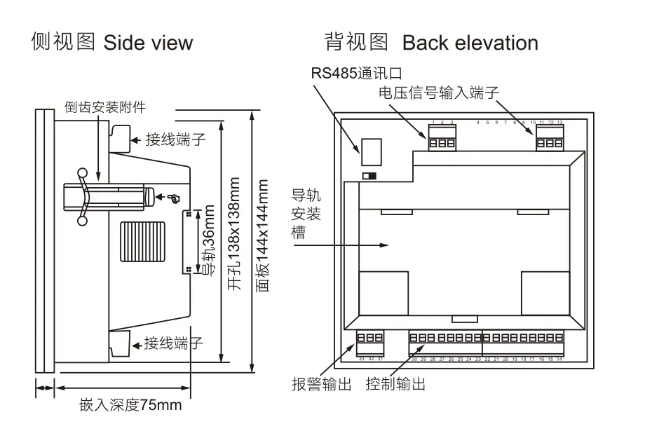
- Current transformer compatibility
The controller must work correctly with the installed CT ratio and input type.
- Reactive power control logic
Different algorithms handle fluctuating loads in different ways.
- Harmonic tolerance
If the system contains non-linear loads, harmonic conditions can affect measurement and switching behavior.
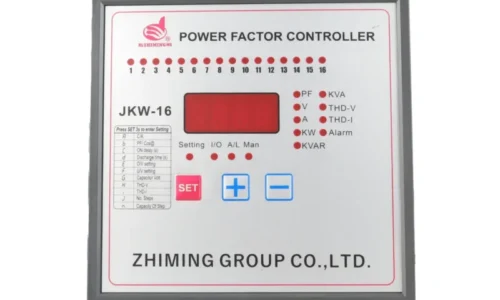
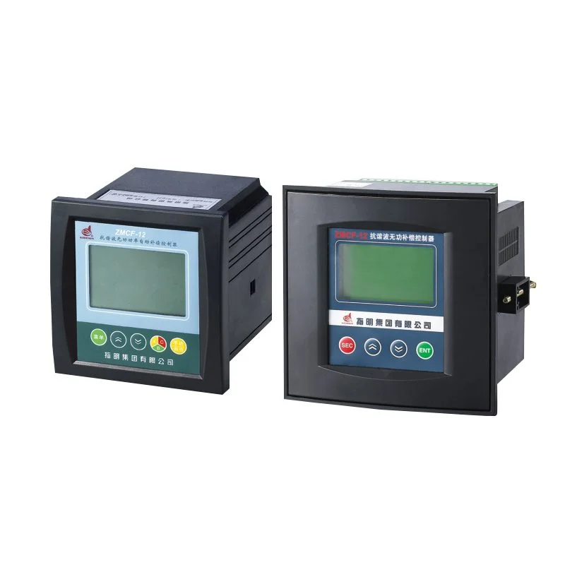
- Display and interface usability
Clear operation menus and readable status indicators make commissioning easier than they sound.
- Communication or expansion options
Useful in more advanced energy monitoring systems.
For more context on how electrical compensation supports broader efficiency goals, the U.S. Department of Energy offers helpful background on industrial energy use, and Schneider Electric’s power factor explanation is a practical reference for the relationship between power factor and system efficiency.
A Simple Feature Comparison by Application
| Application | Load Behavior | What the Controller Should Prioritize | Notes |
|---|---|---|---|
| Manufacturing plant | Variable, motor-heavy | Fast response, stable step control, good protection | Frequent load swings can expose weak logic |
| Commercial building | Moderate, mixed loads | Quiet operation, accuracy, easy settings | Often needs steady day-to-day correction |
| Data center | Sensitive and steady | Reliability, monitoring, clean measurement | System stability matters more than aggressive switching |
| Compressor or welding facility | Highly dynamic | Rapid response, strong protection, harmonic awareness | Load spikes can create switching stress |
This kind of comparison is helpful because it shifts the focus away from generic “best product” language. In reality, the best controller is the one that fits the application cleanly.
Common Mistakes When Choosing a Controller
A few mistakes show up again and again, and they are usually easy to avoid once noticed.
- Choosing by price alone
- Ignoring harmonic distortion
- Forgetting to check capacitor bank compatibility
- Overlooking cabinet temperature and humidity
- Selecting too many or too few switching steps
- Not planning for maintenance access
The price-first approach is especially common, and also the most misleading. A controller that saves a little upfront but causes unstable switching or poor compensation later usually costs more in the long run.
Another subtle issue is assuming every system is “standard.” It often is not. Even two similar facilities can behave differently because of motor duty cycles, seasonal demand, or the way equipment is started and stopped.
Best Practices for Long-Term Performance
Once the controller is installed, long-term performance depends on a few habits. Regular inspection is obvious, but not always followed with enough discipline. Loose wiring, worn contactors, and dusty cabinets can all affect compensation quality.
A practical maintenance routine might include:
- Checking power factor trends monthly
- Verifying capacitor step operation
- Inspecting contactors and wiring
- Confirming ventilation and cabinet cleanliness
- Watching for repeated alarm conditions
If a site has recurring heat or moisture issues, enclosure management matters almost as much as the control logic itself. Supporting equipment, not just the controller, tends to decide how stable the system stays over time.
Where an Automatic Power Factor Controller Fits in a Broader Energy Strategy
It is easy to think of power factor correction as a narrow electrical task, but it usually plays a wider role. Better compensation can reduce electrical losses, improve equipment utilization, and support more predictable plant behavior. In facilities with many motor-driven systems, the benefit often shows up as smoother operation rather than a single dramatic number on a report.
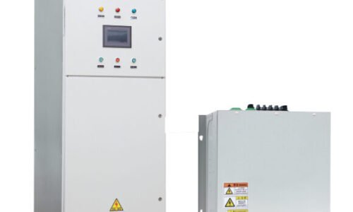
That broader view is also why the controller should be selected as part of a complete compensation architecture, not in isolation. Capacitor sizing, reactor selection where needed, switching devices, enclosure conditions, and monitoring tools all shape the outcome.
In that sense, an reactive power compensation controller is not simply a box that flips capacitors on and off. It is part of the control logic that keeps the entire system practical, efficient, and less prone to avoidable stress.
FAQ
How can a site tell whether its load profile is too unstable for a basic controller?
A quick clue is repeated capacitor switching around the same time each day, or noticeable changes in demand tied to production cycles. If the pattern shifts often and sharply, a more adaptive controller is usually worth considering.
Can power factor correction still be effective in systems with significant harmonics?
Yes, but the controller and surrounding hardware need to be chosen carefully. Harmonics can distort measurements and make switching behavior less reliable, so harmonic conditions should be checked before final selection.
3. What should be verified during commissioning to avoid early problems?
CT orientation, voltage input correctness, capacitor step sequence, alarm settings, and target power factor values are all worth checking. Small setup errors can cause surprisingly large operational issues later.