In industrial electrical systems, certain components quietly shoulder the heavy lifting of maintaining efficiency and power quality. Among these, the power capacitor is arguably the most ubiquitous yet frequently overlooked element. Operating continuously in the background to improve power factor and stabilize voltage, these devices are routinely subjected to harsh electrical and environmental conditions. Because they do not feature moving parts, a dangerous misconception exists that they require little to no maintenance. In reality, a gradual, unseen degradation occurs over time. Neglecting this decline often results in sudden equipment failure, unexpected production downtime, or severe penalty charges from utility providers due to poor power factor. Understanding how these units fail, recognizing the early warnings, and implementing a timely replacement strategy is essential for sustaining long-term operational reliability.
Table des matières
1. Understanding the Core: What Leads to Power Capacitor Degradation?
Every power capacitor installed within a distribution network has a finite operational lifespan, typically governed by the chemical and physical endurance of its internal dielectric materials. While manufacturers design these units to self-heal under minor faults, persistent exposure to adverse operating conditions accelerates internal wear, eventually leading to catastrophic failure.
Thermal Overstress
Excessive heat is the primary catalyst for accelerated insulation aging. When ambient temperatures inside an electrical enclosure exceed design limits—often due to inadequate ventilation, crowded panel layouts, or proximity to heat-generating equipment like variable speed drives—the internal dielectric film begins to dry out.
Furthermore, harmonic currents present in modern industrial grids induce additional internal localized heating, causing the core temperature to climb far beyond safe thresholds. For every 7℃ à 10℃ rise above the maximum rated operating temperature, the expected life expectancy of the dielectric insulation is roughly halved.
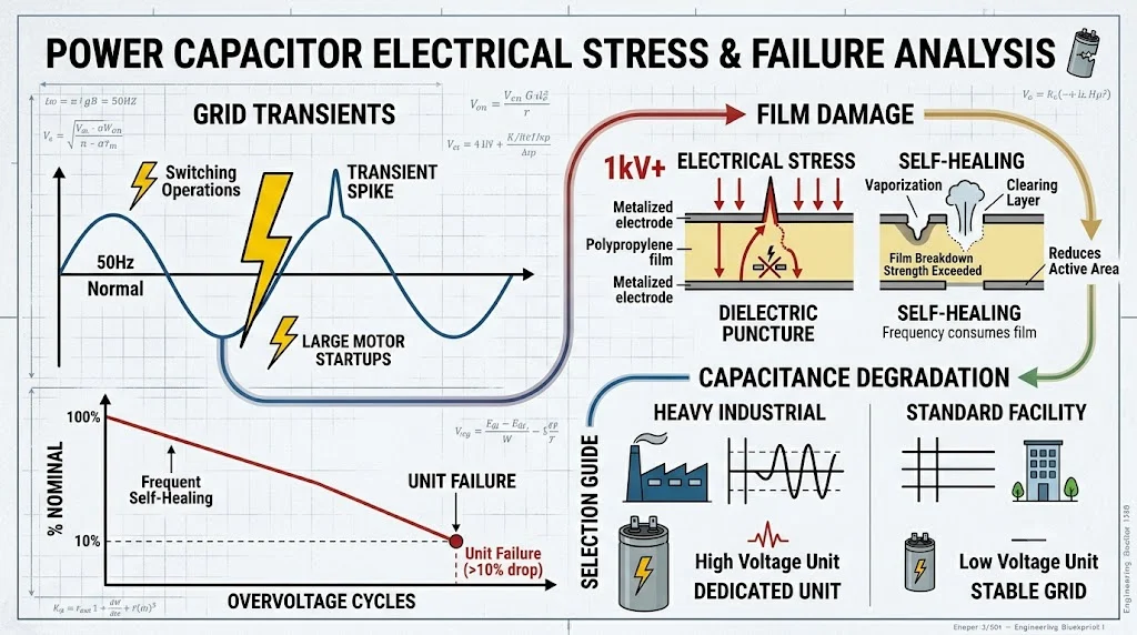
Electrical Stress and Transient Voltages
Industrial power grids are rarely perfectly stable. Switching operations, lightning strikes, and large motor startups generate frequent voltage transients and prolonged overvoltage conditions. When a high voltage spikes across the dielectric layer, it can exceed the material’s breakdown strength.
In modern localized power distribution setups, matching the correct component to the grid’s voltage profile is critical. For instance, in heavy industrial zones experiencing significant voltage fluctuations or utilizing step-up distribution, installing a dedicated condensateur de puissance haute tension ensures the system can withstand these rigorous electrical spikes without experiencing immediate dielectric puncture.
Conversely, in standard commercial facilities or standard motor control centers where lower voltage ranges dominate, utilizing a precisely rated condensateur de puissance à basse tension is the conventional choice to balance power factor correction goals with equipment costs. However, if either type is subjected to repetitive overvoltages exceeding 10% of their nominal rating, the internal self-healing cycles occur too frequently, rapidly consuming the metalized layer and reducing the total available capacitance.
Environmental Contamination
The physical environment surrounding an electrical panel plays a significant role in component longevity. High humidity, conductive dust (such as carbon or metallic particles), and corrosive airborne chemicals can accumulate on the bushings and terminal connections. This contamination creates low-resistance paths, leading to surface tracking, localized arcing, and eventual external flashovers that can rupture the unit’s casing.
2. Common Failure Modes and Their Visible/Invisible Signs
When internal degradation crosses a critical threshold, the component exhibits distinct physical or electrical symptoms. Recognizing these failure modes before they escalate into absolute circuit disruptions prevents minor maintenance issues from turning into catastrophic plant shutdowns.
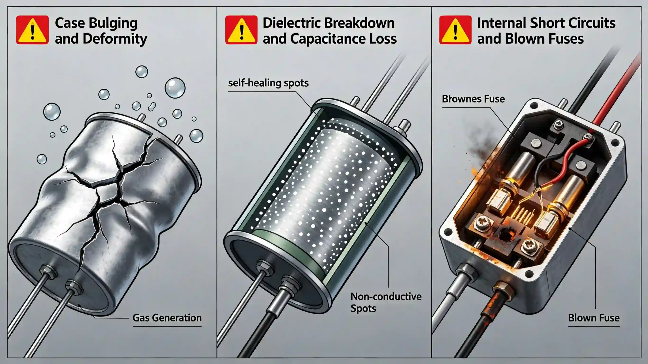
Case Bulging and Deformity
One of the most recognizable physical signs of distress is the swelling or bulging of the capacitor’s outer aluminum or steel container. This occurs because internal electrical arcing or severe overheating causes the dielectric fluid or impregnating wax to decompose, generating gases like hydrogen and carbon monoxide. As gas pressure builds up internally, the metal casing expands. Modern units incorporate an internal overpressure disconnector designed to break the internal connections when the case expands vertically. However, if the expansion happens too violently due to a dead short-circuit, the casing may rupture, leaking oil and posing a fire hazard.
Dielectric Breakdown and Total Loss of Capacitance
Inside a metalized film unit, minor insulation breakdowns are resolved by vaporizing the thin metallic layer around the fault area—a process known as self-healing. While this keeps the unit operational, it leaves behind a tiny non-conductive zone, slightly reducing the total capacitance. Over years of operation, thousands of these micro-healings occur. Eventually, the cumulative loss of active surface area causes the total capacitance to drop significantly below its nominal rating. This loss is completely invisible from the outside; the unit looks perfectly healthy, yet it is no longer contributing effectively to power factor correction.
Internal Short Circuits and Blown Fuses
When a severe, localized dielectric puncture occurs that the self-healing mechanism cannot isolate, an absolute internal short circuit develops. This causes a massive inrush of fault current. If the capacitor bank is equipped with external or internal fuses, these safety devices will blow instantly to isolate the damaged leg. In systems lacking proper fuse coordination or where external protection has been bypassed, an internal short can lead to violent case rupture, damaging adjacent components within the capacitor cubicle.
| Failure Mode | Primary Root Cause | Detection Method | Operational Impact |
|---|---|---|---|
| Case Bulging | Internal gas buildup from oil/film decomposition due to sustained overtemperature. | Visual inspection | High risk of rupture; imminent complete failure. |
| Capacitance Drop | Cumulative self-healing cycles caused by persistent harmonic overcurrents. | Handheld capacitance meter testing | Reduced power factor correction efficiency; utility penalties. |
| Terminal Discoloration | Loose hardware connections leading to localized high contact resistance. | Infrared thermal imaging | High risk of localized fire or phase-to-phase short circuits. |
| Blown Fuses | Severe internal short-circuit or massive transient voltage surge. | Continuity testing / Visual fuse indicator | Complete loss of the affected capacitor phase step. |
3. Diagnostic Techniques: Catching Failures Before Disasters
Relying solely on visual checks is an inadequate strategy for managing electrical infrastructure. A robust predictive maintenance program combines simple physical observations with advanced diagnostic instruments to assess the true internal health of a system’s components.
Infrared Thermography
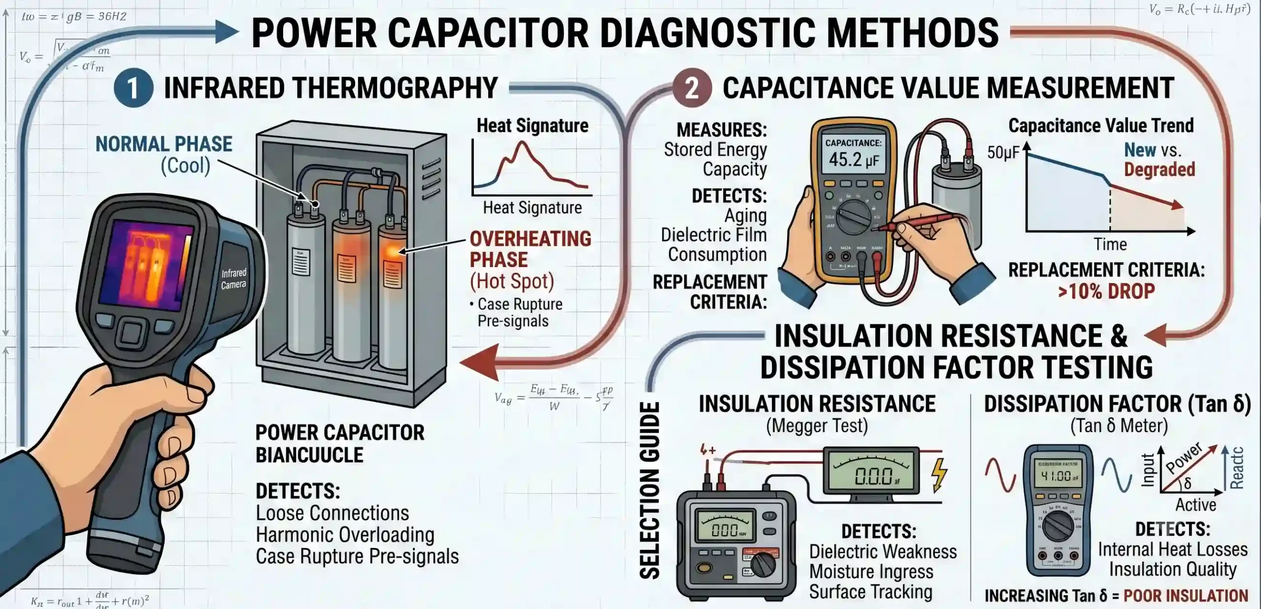
Thermal imaging is an invaluable tool for scanning energized electrical equipment without interrupting operations. During normal service, power capacitors exhibit a uniform, moderate temperature rise above the ambient environment. By utilizing an infrared camera, technicians can easily spot abnormal thermal profiles.
A single unit running significantly hotter than identical parallel units usually indicates high internal losses or severe harmonic loading. Conversely, a unit that appears completely cold while the rest of the bank is warm suggests that the internal overpressure disconnector has already tripped or an upstream fuse has blown, leaving the unit completely offline. Thermography also reveals loose, high-resistance terminal connections, which appear as localized “hot spots” at the wire termination points.
Capacitance Value Measurement
Because capacitance directly dictates the amount of reactive power (kVAR) delivered to the system, regular measurement of this parameter is essential. During planned maintenance shutdowns, technicians isolate the capacitor bank, verify complete discharge, disconnect the parallel busbars, and utilize a high-quality digital capacitance meter across the terminals. A measured value that has dropped by more than 5% à 10% from its initial nameplate value indicates that the internal dielectric film is heavily degraded. According to international electrical maintenance standards, such as those detailed by the International Electrotechnical Commission (IEC), units exhibiting a capacitance drop of this magnitude should be scheduled for immediate replacement to prevent unbalancing the phases.
Insulation Resistance and Dissipation Factor Testing
An insulation resistance tester (commonly referred to as a Megohmmeter) applies a high DC voltage between the shorted terminal leads and the outer metal casing to evaluate the integrity of the isolation barrier. A low insulation resistance reading indicates moisture ingress or severe oil degradation.
Additionally, measuring the dissipation factor provides insight into the dielectric losses within the material. An increasing dissipation factor signifies that more electrical energy is being converted into waste heat inside the capacitor core, accelerating the destructive thermal cycle.
4. Step-by-Step Replacement Guide & Best Practices
When diagnostics reveal that a unit has reached the end of its reliable service life, execution of a precise, safety-focused replacement procedure is required. Working with energy storage devices introduces unique hazards that demand strict adherence to technical protocols.
Step 1: Isolation and Verification of Zero Energy
Never assume a circuit is dead simply because a breaker is tripped. The first and most critical action is to open the main disconnecting switch feeding the capacitor bank and lock it out following standard Lockout/Tagout (LOTO) safety regulations. After isolating the supply, wait a minimum of 5 to 10 minutes. This delay allows the internal discharge resistors to drain the bulk of the high-voltage stored energy down to safe levels (usually below 50V).
Step 2: Safe Manual Discharging and Grounding
Even after waiting for the discharge resistors to work, residual static charges can remain trapped inside individual phases due to broken internal resistor paths. Wearing appropriate arc-flash personal protective equipment (PPE), use a properly rated hot stick equipped with a grounding hook to deliberately short-circuit all terminals together and connect them to the main station ground. This ensures that any residual charge is completely neutralized before human hands touch the connections.
Step 3: Disconnection and Physical Removal
Carefully label and disconnect the power cabling from the terminals. Inspect the cable lugs for signs of heat damage or oxidation; if the copper or aluminum appears brittle or discolored, cut back the wire and crimp on new heavy-duty lugs. Undo the mounting brackets securing the degraded unit to the enclosure shelf and lift it out.
Step 4: Installing and Torqueing the New Unit
Place the new component onto the mounting rack, ensuring adequate physical clearance (typically at least 20mm to 30mm) between adjacent units to facilitate proper convective airflow and natural cooling. Secure the casing to the earth ground bus. When connecting the power cables to the terminals, always use a calibrated torque wrench to tighten the nuts to the exact specification provided by the manufacturer. Loose connections cause high contact resistance and localized heating, while overtightening can crack the ceramic or resin terminal bushings, ruining the new unit instantly.
5. Summary and Conclusion
Maintaining optimal power quality within an industrial facility is a balancing act that requires every component to perform at its nominal specification. As explored, the condensateur de puissance is subject to relentless thermal, electrical, and environmental stresses that steadily degrade its internal structure over time. Whether the deterioration manifests as visible case bulging or remains hidden as a silent drop in total capacitance, the ultimate consequences of ignoring these signals are costly power factor penalties, decreased grid efficiency, and potential safety risks. By embedding regular infrared thermal scans, routine capacitance verification, and precise torqueing practices into your facility’s preventive maintenance playbook, you shift from a reactive state of crisis management to proactive asset preservation. Investing in timely diagnostic inspections and adhering to structured replacement steps guarantees that your power distribution network remains safe, stable, and highly efficient for years to come.
FAQ
How does ambient temperature affect the life expectancy of a standard Power Capacitor?
Ambient temperature is one of the most critical external variables governing the lifespan of these units. The internal insulation materials, usually consisting of metalized polypropylene film, are highly sensitive to thermal degradation. Operating a unit in an environment that continuously runs just 8℃ above its maximum design rating will accelerate the chemical breakdown of the film, effectively cutting its operational lifespan in half. This makes proper ventilation, clean enclosure air filters, and adequate physical spacing between individual canisters absolute operational necessities for avoiding premature failure.
If a metalized film Power Capacitor has self-healing properties, why does it eventually fail?
The self-healing mechanism is an excellent engineering solution for preventing immediate catastrophic shorts, but it is not an infinite remedy. Each time a localized dielectric puncture occurs, a tiny spark vaporizes a minute section of the aluminum-zinc metallization to isolate the fault. While this action successfully clears the short circuit and allows the unit to keep functioning, it permanently removes a small fraction of the conductive surface area. Over years of service, thousands of these micro-healings accumulate, causing a gradual but permanent drop in total capacitance. Once the overall capacitance falls below 90% of its original nameplate specification, the unit can no longer fulfill its intended power factor correction role and must be replaced.
Can high harmonic distortion cause a capacitor bank to rupture, and how can this be prevented?
Yes, harmonic distortion is a frequent driver behind sudden casing ruptures. Capacitors naturally exhibit low impedance at high frequencies . Consequently, when harmonic voltages (such as the 5th, 7th, or 11th harmonics produced by non-linear loads like VFDs and rectifiers) are present on the grid, the unit acts like a magnet for these high-frequency currents. This harmonic current overload creates intense internal thermal stress. If the total current exceeds the unit’s maximum overcurrent capability, the internal dielectric materials rapidly decompose into gas, causing the casing to swell and eventually rupture if protective fuses or overpressure disconnectors fail to clear the fault in time. To prevent this, facilities with high harmonic distortion should install tuning reactors in series with the units to form a detuned filter system.