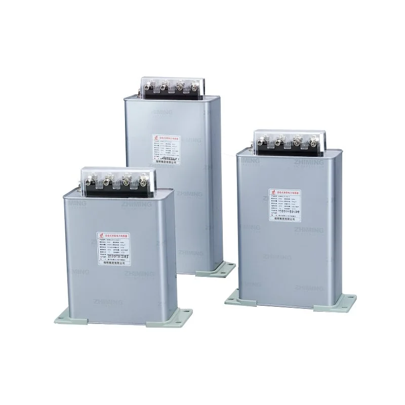
Power factor correction is one of those topics that sounds niche until the electricity bill starts creeping up, motors seem less responsive than expected, or a plant keeps fighting avoidable losses. In practice, a **Power Factor Correction Capacitor** is often a quiet fix in the background, helping electrical systems run more efficiently and reducing unnecessary reactive power. That said, the hardware is only part of the story. Installation quality, safety checks, and ongoing inspection tend to decide whether the setup performs smoothly or becomes one more maintenance headache.
A capacitor bank is not something to rush into place and hope for the best. The better installations usually look almost unremarkable from the outside, which is probably the point. They are planned carefully, mounted correctly, wired with discipline, and tested before full operation. That kind of detail is what this checklist is for.
جدول المحتويات
Understanding the Role of a Power Factor Correction Capacitor
A power factor correction capacitor supports electrical systems by offsetting inductive loads, especially in facilities with motors, transformers, compressors, or large HVAC equipment. In simple terms, it helps reduce the reactive component of current, which can improve system efficiency and ease the burden on supply infrastructure.
In real-world settings, the need for correction often shows up in indirect ways:
- Higher utility penalties
- Overloaded feeders or transformers
- Lower-than-expected voltage at the load
- Warm equipment that seems to be working harder than it should
Not every site needs the same solution, though. The right capacitor depends on load profile, voltage level, and whether the system has harmonics or switching transients. For that reason, product selection matters just as much as installation.
Facilities evaluating a broader range of correction equipment often review product families like the Power Factor Correction Capacitor options available for different system sizes and configurations. The main thing is to match the unit to the actual operating conditions rather than the “ideal” conditions on paper.
Before Installation: Safety and Planning Checklist
This part is sometimes rushed, which is a pity, because most avoidable issues start before a screwdriver even touches the panel.
Review system requirements
Before anything is mounted, confirm what the electrical system actually needs:
- الجهد المقنن
- تردد النظام
- Load type and duty cycle
- Ambient temperature
- Harmonic content
- Switching frequency
A capacitor bank that works beautifully in a stable low-distortion environment may behave poorly in a plant with VFDs, welders, or frequent load variation. That is where the distinction between standard units and specialized designs becomes important. In higher-demand systems, a مكثف طاقة عالية الجهد العالي may be more appropriate than a general-purpose unit.
Inspect the site and equipment
The installation area should be checked with a slightly skeptical eye. Good equipment can still fail early if the surroundings are poor.
Look for:
- Enough clearance around the cabinet or mounting point
- Clean airflow paths
- A dry and stable location
- Solid grounding points
- No damaged cables or corroded terminals nearby
Also inspect the existing protective devices. Fuses, contactors, and insulation condition should all be verified before the new capacitor is added into the circuit.
Gather protective equipment and tools
A proper safety setup usually includes:
- Lockout/tagout equipment
- Insulated tools
- Voltage tester
- Discharge stick or discharge resistor setup
- PPE rated for the electrical environment
- Torque tools for terminal tightening
The exact PPE depends on voltage and arc-flash risk, of course, but skipping this step is rarely a smart trade.
Confirm product specifications
This is where mismatch problems tend to show up. Check that the capacitor’s:
- Voltage rating fits the system
- kvar output matches the correction target
- Enclosure type suits the environment
- Discharge characteristics are suitable
- Mounting style fits the available space
For shunt compensation applications, a high voltage shunt power capacitor may be part of the correct configuration, especially where reactive power support is needed directly on the bus or feeder.

Step-by-Step Installation Process
The actual installation is usually straightforward, but only when each step is done in order.
Step 1: Isolate and de-energize the circuit
This is not the step to improvise on.
- Shut down the relevant circuit
- Apply lockout/tagout procedures
- Verify zero voltage with an approved meter
- Allow discharge time before touching terminals
Capacitors can hold dangerous charge even after power is removed, so “off” does not automatically mean safe.
Step 2: Mount the capacitor securely
Once the area is confirmed safe, mount the unit according to the manufacturer’s instructions. A few details matter more than they first appear:
- Keep the unit upright if required
- Maintain airflow around the enclosure
- Avoid mounting near excessive heat sources
- Reduce vibration where possible
- Leave room for future inspection and cable access
A neatly mounted capacitor tends to stay cooler and is easier to service. That is a practical advantage, not just a cosmetic one.
Step 3: Wire the unit correctly
Wiring errors are among the most expensive “small” mistakes in electrical work.
Before connecting:
- Confirm phase sequence if applicable
- Tighten terminals to the recommended torque
- Use appropriately rated conductors
- Bond grounding properly
- Check insulation integrity before energizing
If the system uses a capacitor bank with shunt compensation, make sure the wiring layout matches the intended configuration. In that context, a مكثف طاقة تحويلة الجهد العالي may be connected as part of a larger correction stage rather than as a standalone piece of equipment.
Step 4: Connect protective components
Capacitors rarely operate best when left alone. Protective hardware improves reliability and helps prevent nuisance failures.
Common supporting components include:
- Fuses or circuit breakers
- Contactor or switching device
- Discharge resistors
- Surge protection
- Detuning reactors in harmonic-heavy systems
In systems with variable loads or significant harmonic distortion, those extras are often the difference between long service life and recurring trips.
Step 5: Double-check before energizing
Before restoring power, inspect the installation line by line. A slow final review can prevent a very fast failure.
Check for:
- Loose terminals
- Incorrect conductor placement
- Missing labels
- Obstructed airflow
- Damaged insulation
- Abnormal odor, dents, or swelling
At this point, a second pair of eyes is genuinely useful. Electrical installations have a way of revealing small mistakes only after energization, which is not ideal.
Installation Checklist Table
| البند | What to Verify | Why It Matters |
|---|---|---|
| Voltage rating | Matches system voltage | Prevents overstress and premature failure |
| Mounting location | Ventilated, stable, accessible | Helps cooling and maintenance |
| Wiring | Correct phase, torque, and grounding | Reduces fault risk |
| Protective devices | Fuses, breakers, reactors, contactors | Improves operational safety |
| Discharge path | Proper discharge time and resistors | Protects personnel during service |
| Environmental conditions | Heat, dust, moisture, vibration | Affects service life and reliability |
Safety Checklist After Installation
The first startup is not the finish line; it is the beginning of the observation period.
Initial energizing
Bring the system online in stages if possible. Watch for:
- Unusual current spikes
- Audible buzzing or humming
- Excessive heating
- Unexpected relay behavior
- Rapid tripping or instability
A slight sound or minor temperature rise can be normal, but sharp changes deserve attention.
Monitor during the first operating cycle
After installation, the capacitor should be checked under actual load conditions. That usually means observing the system during normal production, not just during a quiet test window.
Look for:
- Stable voltage improvement
- Reduced reactive demand
- No abnormal leakage
- No visible deformation
- Acceptable surface temperature
If readings drift or the bank behaves unpredictably, isolate it and investigate before continuing.
Common Mistakes to Avoid
Some installation errors keep reappearing, even in well-run facilities:
- Selecting the wrong voltage class
- Ignoring harmonic content
- Mounting in a poorly ventilated space
- Forgetting discharge verification
- Tightening terminals unevenly
- Skipping periodic inspection
One of the more common oversights is assuming that all capacitors are interchangeable. They are not. A high-voltage industrial site needs different handling than a small commercial panel, and the difference is often visible in the equipment itself.
Maintenance Tips for Longer Service Life
A correctly installed capacitor still needs occasional attention. The best maintenance routines are simple and consistent.
- Inspect for swelling, oil leakage, or discoloration
- Clean dust from ventilation paths
- Check terminal tightness on scheduled intervals
- Measure temperature rise during operation
- Confirm that protection devices remain functional
If the system runs in a harsh environment, inspections should happen more often. Heat and contamination are not subtle over time.
For broader electrical safety practices, OSHA’s electrical safety guidance is a useful reference point, especially for lockout/tagout discipline and safe work procedures. For technical planning around power quality and capacitor application, IEEE-related standards and guidance are also widely respected in the industry, and IEEE Xplore is a practical starting place for deeper study.
الخاتمة
Installing a Power Factor Correction Capacitor is not complicated in theory, but the details matter enough to change the outcome quite a bit. The safest and most reliable installations usually come from careful planning, correct product selection, disciplined wiring, and patient testing afterward. That approach may feel slower at first, though it tends to save time later by preventing failures, overheating, and unnecessary downtime.
In other words, the capacitor itself is only part of the solution. The checklist around it is what makes the solution work.
الأسئلة الشائعة
How can a capacitor’s performance be affected by nearby drive equipment?
Variable speed drives can introduce harmonic distortion, which may change how a capacitor bank behaves. In some cases, detuning or filtering is needed so the correction system does not amplify unwanted currents.
What indicates that a capacitor bank may need inspection sooner than scheduled?
Frequent fuse operations, unusual cabinet heat, rising noise levels, or inconsistent power factor readings are all signs that the system deserves an earlier check.
Can a correction capacitor be added to an existing installation without redesigning the entire panel?
Sometimes yes, but only if the electrical space, protection scheme, and load profile are suitable. Older systems often need at least a partial review before an additional unit is introduced.