لا تعمل معظم الأنظمة الكهربائية بمعامل قدرة واحد. هذا هو الواقع. الأحمال الحثية - المحركات، والمحولات، والإضاءة الفلورية - تسحب الطاقة التفاعلية من الإمداد، مما يؤدي إلى انخفاض معامل القدرة. والنتيجة هي تيار أعلى، وخسائر أكثر، وغالبًا ما تكون فاتورة الكهرباء أكبر من اللازم.
صنع تصحيح معامل القدرة العمل ليس معقدًا للغاية، ولكنه يتطلب بعض الفهم للنظام، والأحمال المتضمنة، والمعدات المناسبة للمهمة. إنها واحدة من تلك الأشياء التي تبدو واضحة على الورق ولكنها تنطوي على بعض الفروق الدقيقة في الممارسة العملية التي يسهل التغاضي عنها.
جدول المحتويات
فهم الحاجة إلى تصحيح معامل القدرة
قبل تثبيت أي شيء، من المفيد فهم ما يحدث بالفعل. عندما يكون معامل القدرة منخفضًا (لنقل 0.7 أو 0.75)، فإن جزءًا كبيرًا من التيار المتدفق عبر النظام لا يقوم بأي عمل مفيد. إنه فقط يدور ذهابًا وإيابًا بين المصدر والحمل، مما يؤدي إلى تسخين الكابلات واستهلاك سعة المحول على طول الطريق. A محول تيار الجهد المنخفض سيُسجِّل هذا الحجم المتضخم للتيار المثبت على المغذي الرئيسي بأمانة، على الرغم من أن معظم ما يقيسه يمثل طاقة تفاعلية مهدرة بدلاً من الكيلووات الفعلية التي يتم توصيلها.
تلاحظ المرافق هذا الأمر. ويفرض العديد منها رسومًا على الطاقة التفاعلية أو غرامات على معامل القدرة بمجرد انخفاضه إلى أقل من الحد الأدنى - عادةً ما يكون حوالي 0.9 أو 0.95 حسب المنطقة. لذلك هناك حافز مالي مباشر لتصحيحه، بخلاف الفوائد الفنية فقط.
خطوات لجعل تصحيح معامل القدرة فعالاً
الخطوة 1 - قياس معامل القدرة الحالي
هذا هو المكان الذي يبدأ منه كل شيء. فبدون قياسات دقيقة، فإن أي جهد للتصحيح هو في الأساس تخمين. يمكن أن يوفر محلل جودة الطاقة أو حتى مقياس بسيط مزود بمقياس مشبك بسيط مع إمكانية قراءة معامل القدرة بيانات خط الأساس.
الأشياء الرئيسية التي يجب قياسها:
الطاقة النشطة (كيلوواط)
الطاقة التفاعلية (كيلو فولت تيار متردد)
الطاقة الظاهرة (كيلو فولت أمبير)
معامل القدرة الحالي (متأخر أو متقدم)
الخطوة 2 - تحديد التصحيح المطلوب
بمجرد معرفة معامل القدرة الحالي، يجب تحديد معامل القدرة المستهدف. وتهدف معظم المنشآت إلى تحقيق شيء يتراوح بين 0.95 و0.99. ومن هناك، يمكن حساب تعويض القدرة التفاعلية المطلوبة.
الصيغة قياسية إلى حد ما:
kVAR المطلوب = kW × (tan φ ₁ - tan φ ₂)
حيث φ ₁ هي الزاوية المناظرة لعامل القدرة الحالي و φ ₂ يناظر الهدف.
الخطوة 3 - اختر معدات التصحيح
وهنا يأتي دور الخيارات. تشمل الخيارات الأكثر شيوعاً ما يلي:
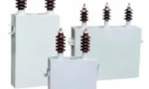
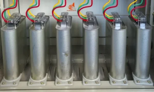
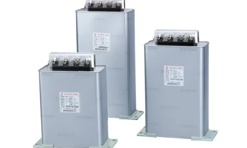
بنوك المكثفات الثابتة - مناسبة للأحمال الثابتة
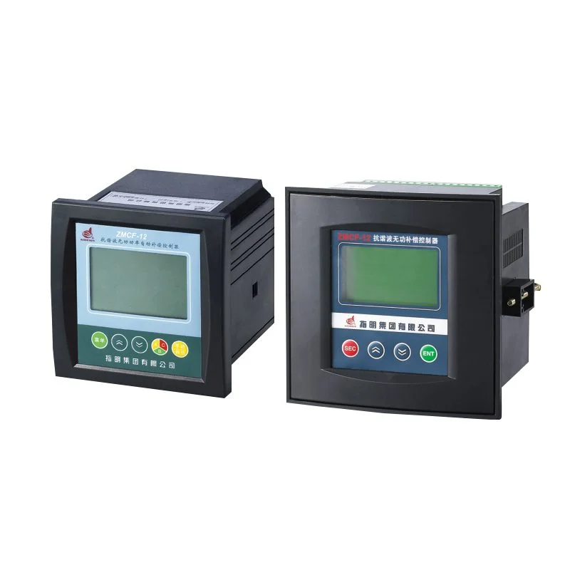
لوحات تصحيح معامل القدرة التلقائي (APFC) - للأحمال المتغيرة
المفاعلات غير المضبوطة مع المكثفات - للأنظمة ذات التشوه التوافقي
المرشحات التوافقية النشطة - لبيئات الأحمال المعقدة وغير الخطية
لكل منها مكانه. بالنسبة لمنشأة ذات أحمال محركات ثابتة تعمل على مدار الساعة، قد تكون المكثفات الثابتة مناسبة تمامًا. ولكن بالنسبة لمنشأة مثل مصنع تصنيع حيث تتغير الأحمال على مدار اليوم، فإن لوحة APFC ذات مراحل المكثفات المتعددة تكون أكثر منطقية.
الخطوة 4 - التثبيت والتشغيل
موقع التركيب مهم أكثر مما يدركه الناس في بعض الأحيان. يمكن تركيب معدات تصحيح معامل القدرة في:
الإمداد الرئيسي الوارد (التصحيح المركزي)
لوحات التوزيع (تصحيح المجموعة)
أطراف المحرك الفردي (تصحيح محلي)
التصحيح المركزي أبسط وأرخص في الصيانة ولكنه لا يقلل من الخسائر داخل شبكة التوزيع الداخلية. يزيل التصحيح المحلي في كل محرك الخسائر الداخلية ولكنه يكلف أكثر مقدمًا. ويقع التصحيح الجماعي في مكان ما بينهما - وهو حل وسط معقول للعديد من الإعدادات.
الأخطاء الشائعة في تصحيح معامل القدرة
حتى مع وجود النوايا الحسنة، يمكن أن تنحرف الأمور عن مسارها. بعض المشاكل التي تظهر بانتظام
التصحيح الزائد الذي يؤدي إلى عامل طاقة رائد، والذي تعاقب عليه بعض المرافق أيضًا
تركيب المكثفات على أنظمة ذات محتوى توافقي عالٍ دون مفاعلات فصل التوافقيات - يمكن أن يتسبب ذلك في حدوث رنين وحتى تعطل المكثف
تجاهل عابرات التبديل التي تحدث عند تعشيق مراحل المكثف
عدم أخذ تغيرات الأحمال المستقبلية في الحسبان، مما يجعل النظام غير مصحح في غضون عام أو عامين
إنه نوع من الأمور التي يؤدي فيها القليل من التحليل المسبق إلى توفير الكثير من المتاعب لاحقًا. يؤدي التسرع في الحل دون بيانات قياس مناسبة دائمًا إلى نتائج دون المستوى الأمثل.
الأسئلة الشائعة
ما هي المدة التي يستغرقها تصحيح معامل القدرة حتى يؤتي ثماره؟
في معظم الحالات، تتراوح فترة الاسترداد بين 12 و24 شهرًا. وغالبًا ما تشهد المنشآت التي تعاني من عقوبات الطاقة التفاعلية الثقيلة عوائد أسرع. ويعتمد الجدول الزمني الدقيق على هيكل أسعار المرافق وحجم نظام التصحيح المركب.
هل يمكن أن يؤدي تصحيح معامل القدرة إلى تلف المعدات؟
إذا تم القيام به بشكل غير صحيح، نعم. يمكن أن تتعرض المكثفات المثبتة على الأنظمة ذات التشوه التوافقي الكبير للسخونة الزائدة أو الرنين. لهذا السبب يجب أن يكون التحليل التوافقي جزءًا من التقييم قبل اختيار أي معدات تصحيح.
هل يقلل تصحيح معامل القدرة من الاستهلاك الفعلي للطاقة؟
ليس بشكل مباشر - فهو يقلل من الطاقة التفاعلية وليس الطاقة النشطة. ومع ذلك، من خلال خفض إجمالي التيار في النظام، فإنه يقلل من خسائر I²R في الكابلات والمحولات. لذلك هناك انخفاض صغير ولكنه حقيقي في الطاقة المهدرة كحرارة، بالإضافة إلى الوفورات المالية الناتجة عن تجنب الغرامات.