Choosing the right capacitor bank is not just a matter of buying a cabinet with enough kVAr printed on the nameplate. In real electrical systems, the “right” solution depends on load behavior, harmonic conditions, voltage level, switching frequency, utility requirements, protection design, and even the temperature of the room where the equipment will sit.
A capacitor bank that is properly selected can improve power factor, reduce reactive power demand, release transformer capacity, lower current in cables, and help stabilize voltage. A poorly selected one, however, may overcompensate the system, amplify harmonics, trip protection devices, or fail earlier than expected.
If you want to understand the practical value before reviewing the selection details, this article on Benefits Of Installing A Capacitor Bank explains how capacitor banks can support power factor improvement, energy efficiency, voltage stability, and electrical system performance.
For readers who want a basic explanation before going deeper into selection, this guide on what is a capacitor bank. is a useful starting point. The article below focuses more on the practical buying and engineering decisions: what to check, what to avoid, and how to match the equipment to actual site conditions.
جدول المحتويات
Start with the Real Problem You Need to Solve
Before selecting a capacitor bank, it helps to define the main problem. Different problems point toward different types of equipment.
Power Factor Penalties
This is the most common reason facilities install capacitor banks. Many utilities charge extra when the power factor drops below a specified level, such as 0.90 or 0.95. A low power factor means the utility must deliver more current for the same amount of useful power.
In this case, the goal is usually clear: raise the power factor from the current value to the target value required by the utility contract. The capacitor bank must be sized carefully so it provides enough kVAr during normal operation without pushing the system into a leading power factor during light-load periods.Voltage Drop or Poor Voltage Stability
In facilities with long cable runs, large motors, or heavy intermittent loads, voltage drop can become noticeable. Motors may run hotter, lights may flicker, and sensitive equipment may show instability.
Reactive power compensation can help improve voltage conditions, especially when installed near the load. However, voltage support applications need more care than simple bill reduction. Load changes, feeder impedance, and switching steps all affect the result.Transformer or Cable Overloading
Reactive current occupies capacity in transformers, busbars, and cables. If a transformer is near its limit but much of the current is reactive, a capacitor bank may release some usable capacity. This does not magically increase the transformer’s thermal rating, but it can reduce unnecessary current flow and postpone expensive upgrades in some cases.
Harmonic Distortion and Power Quality Issues
Modern facilities often have nonlinear loads. These include:
- Variable frequency drives
- Soft starters
- UPS systems
- Rectifiers
- ماكينات اللحام
- أفران الحث الحثي
- LED lighting drivers
- Computer power supplies
Understand the Main Types of Capacitor Banks
بنك المكثفات الثابتة
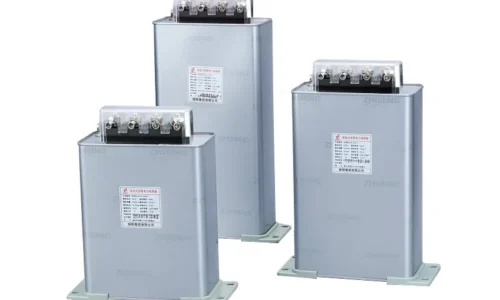
A fixed capacitor bank provides a constant amount of reactive power whenever it is connected. It is simple, reliable, and usually lower in cost.
It is suitable for:
– Constant-speed motors – Stable production loads – Transformers requiring no-load compensation – Loads that operate for long periods at a predictable level The main disadvantage is the risk of overcompensation. When the load decreases but the capacitor bank remains connected, the system may shift toward a leading power factor. That can cause voltage rise and may violate utility requirements.Automatic Capacitor Bank
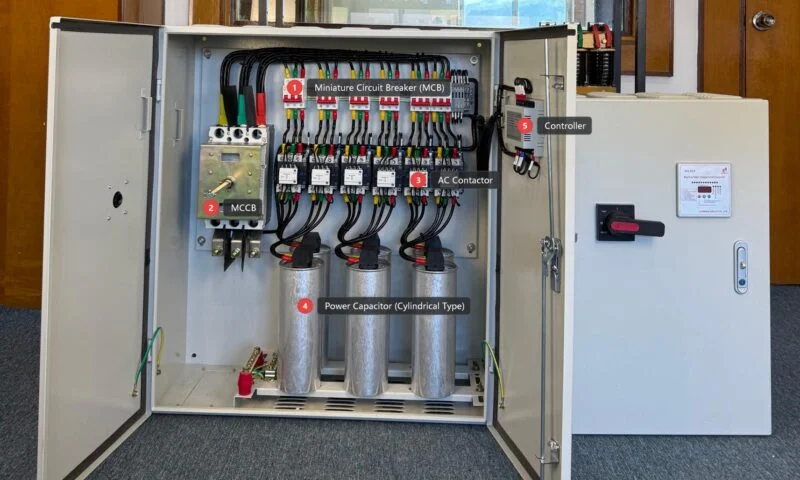
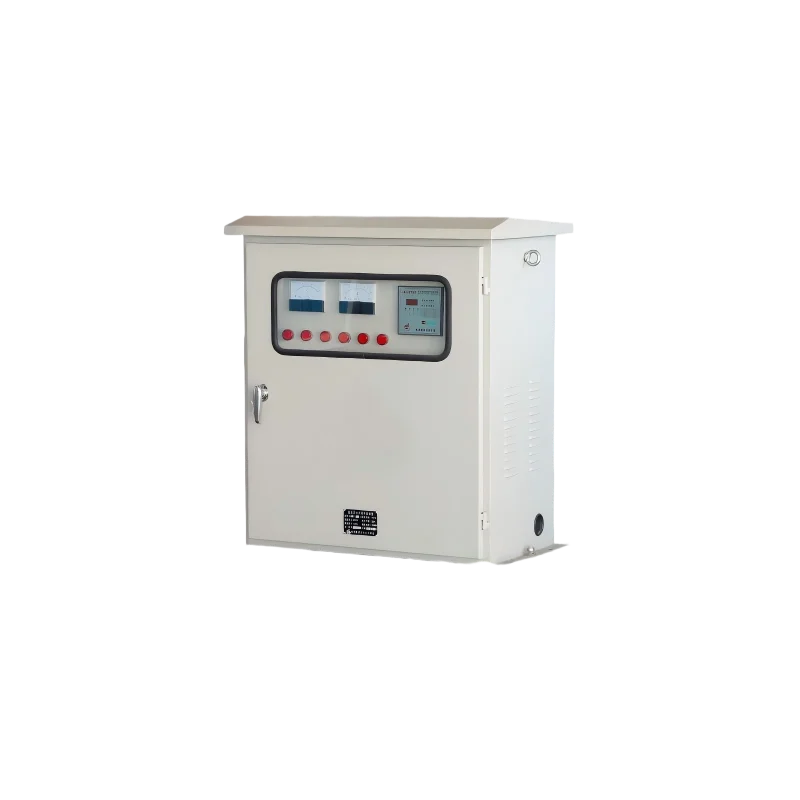
An automatic capacitor bank uses a power factor controller to switch capacitor stages on and off according to demand. Instead of supplying one fixed kVAr value, it adjusts compensation in steps.
This is often the preferred choice for:- Factories with changing production schedules
- Commercial buildings with variable HVAC demand
- Workshops where machines start and stop throughout the day
- Facilities trying to maintain a target power factor automatically
Detuned Capacitor Bank
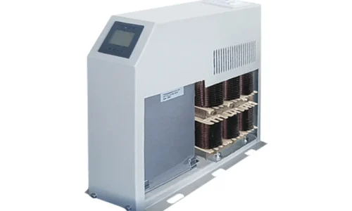
A detuned capacitor bank includes series reactors. These reactors shift the resonant frequency of the capacitor bank away from common harmonic frequencies, reducing the risk of resonance.
Detuned banks are commonly used where nonlinear loads are present. They are not the same as full harmonic filters, but they are often a practical and cost-effective solution for preventing harmonic amplification.
A detuned system may be recommended when: – Many VFDs are installed – Capacitors have failed before – Transformer noise or overheating is present – Harmonic distortion has been measured – The facility has rectifiers, UPS systems, or welding loadsHarmonic Filter Capacitor Bank
A harmonic filter capacitor bank is engineered to absorb or reduce specific harmonic orders. It is more specialized than a standard detuned bank and usually requires detailed harmonic analysis.
These systems are used in heavy industrial environments such as steel, mining, petrochemical, large drive systems, and plants with strict power quality requirements.
Thyristor-Switched Capacitor Bank
A thyristor-switched capacitor bank uses semiconductor switching instead of mechanical contactors. It can respond very quickly to load changes and avoids mechanical wear from frequent operation.
It is suitable for: – Cranes – Elevators – Welding machines – Rolling mills – Rapidly fluctuating loads – Dynamic reactive power compensation The tradeoff is higher cost and greater sensitivity to thermal design. For normal slowly varying loads, a contactor-switched automatic bank may still be more economical.Low Voltage or High Voltage Capacitor Bank?
Voltage level is one of the first practical decisions. The best choice depends on where compensation is needed and how the electrical distribution system is arranged.
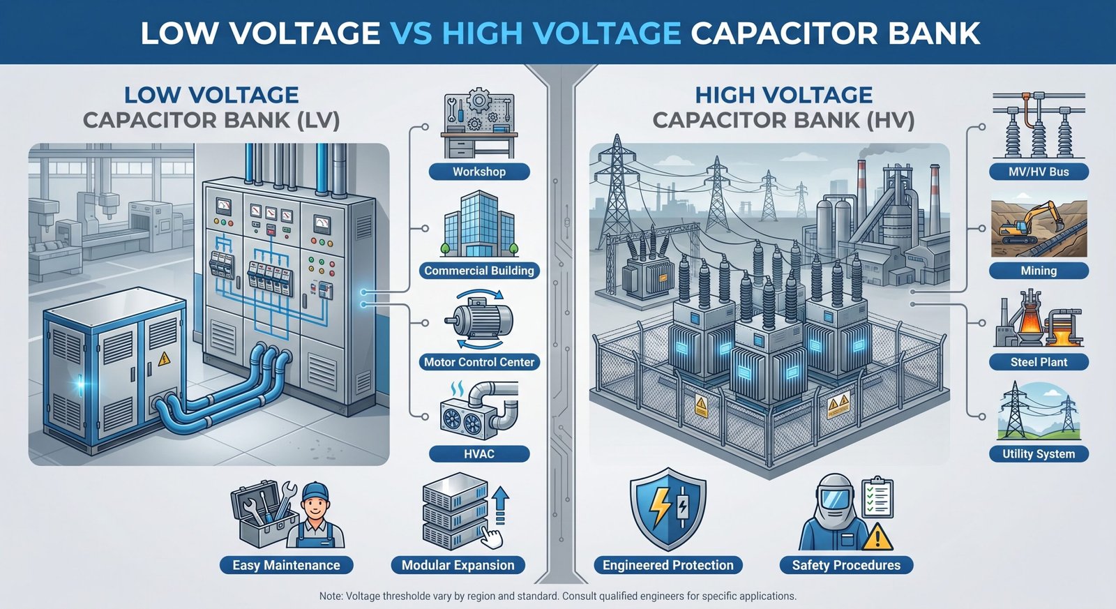
When to Choose a Low Voltage Capacitor Bank
- المباني التجارية
- Small and medium factories
- Workshops
- أنظمة التدفئة والتهوية وتكييف الهواء
- Low-voltage motor loads
- Localized power factor correction
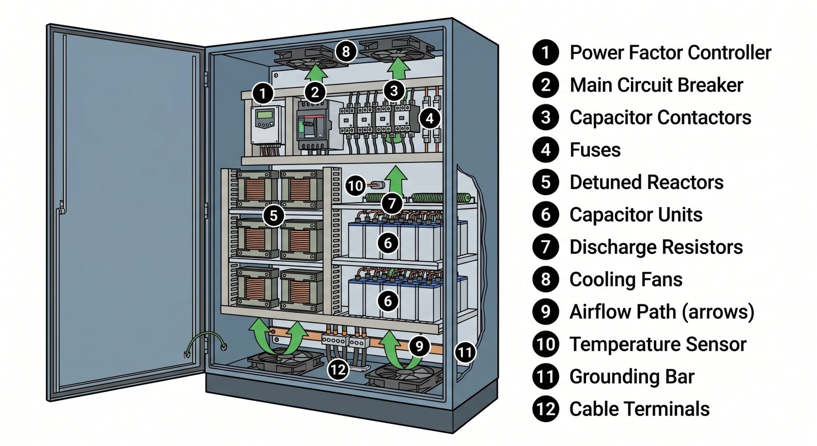
When to Choose a High Voltage Capacitor Bank
A high voltage بنك المكثفات is typically installed at the medium-voltage or high-voltage bus level. It is often used in substations, mining operations, steel plants, petrochemical facilities, utility networks, and large industrial distribution systems. High-voltage compensation can be more efficient when large blocks of reactive power are needed at the main bus. However, it requires more rigorous insulation coordination, switching equipment, protection relays, discharge systems, and safety procedures.
Low Voltage vs High Voltage Capacitor Bank
| Selection Factor | Low Voltage Capacitor Bank | High Voltage Capacitor Bank |
|---|---|---|
| Typical location | LV distribution panel, MCC, load side | MV/HV bus, substation, main feeder |
| Common applications | Buildings, workshops, factories | Utilities, mines, steel plants, heavy industry |
| Maintenance access | Easier and more familiar for site teams | Requires stricter safety procedures |
| Initial cost | Usually lower | Higher due to insulation and protection |
| Expansion flexibility | Often modular and simple | Requires more engineering review |
| Protection complexity | معتدل | More complex, often relay-based |
| Best use case | Local or distributed compensation | Large centralized reactive power support |
In many large facilities, the final design may use both: high-voltage compensation at the main bus and low-voltage compensation near large load groups.
How to Calculate the Required kVAr Capacity
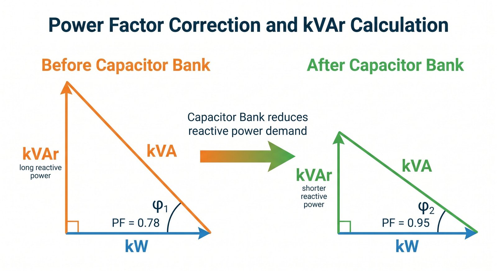
The kVAr rating is one of the most important parts of capacitor bank selection. Too little compensation will not solve the power factor problem. Too much compensation can create new issues.
Basic Data You Need First
Before calculating the required capacity, collect the following information:
- System voltage and frequency
- Existing power factor
- Target power factor
- Active power demand in kW
- Maximum demand from utility bills
- Load profile over a typical day or week
- Transformer rating and loading
- Harmonic distortion measurements, if available
- Future expansion plans
Common kVAr Calculation Method
A common formula is:
Required kVAr = kW × (tan φ1 − tan φ2) Where:- φ1 is the angle corresponding to the existing power factor
- φ2 is the angle corresponding to the target power factor
- kW is the active power demand
- Active demand: 500 kW
- Existing power factor: 0.78
- Target power factor: 0.95
Avoid Oversizing the Capacitor Bank
There is a common but risky assumption that “more kVAr is better.” It is not. Oversizing can create a leading power factor, especially during low-load periods. That may cause:
- Voltage rise
- Utility non-compliance
- Unstable controller operation
- Increased capacitor stress
- Nuisance tripping
- Poor interaction with generators or transformers
Practical Sizing Guidance
| Existing Power Factor | معامل القدرة المستهدف | Approximate Compensation Need | Practical Note |
|---|---|---|---|
| 0.70 | 0.95 | عالية | Careful staged compensation needed |
| 0.80 | 0.95 | Medium-high | Common industrial correction case |
| 0.85 | 0.95 | متوسط | Usually manageable with automatic bank |
| 0.90 | 0.95 | Lower | Avoid oversizing |
| 0.95 | 0.98 | Modest | Check whether improvement is financially useful |
This table is only a general guide. Final sizing should be based on actual kW and power factor data.
Match the Capacitor Bank to Your Load Profile
A capacitor bank should follow the behavior of the electrical load. This is where many selection mistakes happen.
Stable Loads
Stable loads include pumps, fans, compressors, and constant-speed motors that run for long periods. These loads may be suitable for fixed capacitor compensation or simple automatic compensation.
For example, a large motor that operates continuously may have a dedicated capacitor bank installed near it. This can reduce current in the upstream feeder. Still, motor starting, switching transients, and manufacturer recommendations should be checked.
Variable Loads
Most factories have variable loads. Machines start and stop, production lines change speed, and operating shifts affect total demand.
For these facilities, an automatic capacitor bank is usually more practical. It allows the compensation level to rise and fall with the load. The controller monitors power factor and switches capacitor stages as needed.Rapidly Fluctuating Loads
Some loads change too quickly for mechanical contactor switching. Examples include:
- Spot welders
- Cranes
- Elevators
- Rolling mills
- Large presses
- Arc furnaces
Nonlinear Loads
Nonlinear loads deserve special attention. If a facility has many VFDs, UPS systems, rectifiers, or inverter-based equipment, a standard capacitor bank may be vulnerable to harmonic resonance.
A practical rule is simple: if nonlinear loads make up a meaningful portion of the total load, harmonic measurement should be performed before choosing the capacitor bank. Detuned reactors or harmonic filters may be necessary.Do Not Ignore Harmonics and Resonance
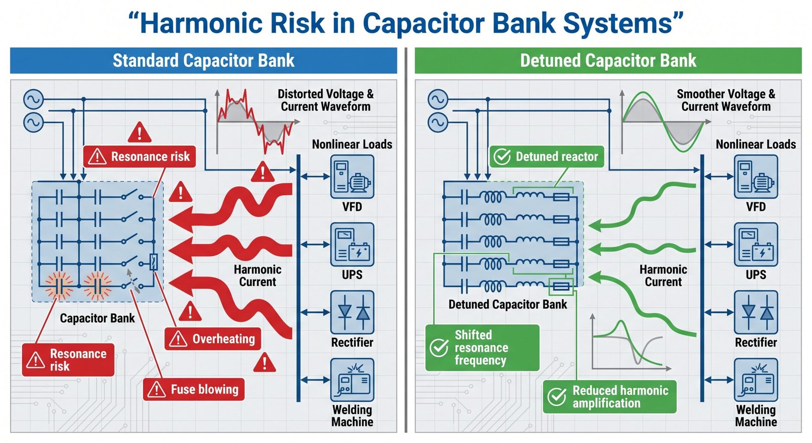
Harmonics are one of the biggest reasons capacitor banks fail prematurely. This problem is not always visible at first. The equipment may run normally for weeks or months, then fuses begin to blow, capacitors swell, contactors fail, or cabinet temperature rises.
Why Harmonics Change the Selection
Capacitors have lower impedance at higher frequencies. Harmonic currents can therefore flow into capacitors more easily than expected. When the system inductance and capacitance resonate near a harmonic frequency, current can be amplified.
Possible symptoms include:- Overheated capacitor units
- Noisy reactors or transformers
- Frequent fuse operation
- Burned contactors
- Controller alarms
- Distorted voltage waveform
- Short capacitor service life
When a Detuned Reactor Is Recommended
A detuned reactor is often recommended when:
– VFDs represent a significant share of the load
– Harmonic voltage distortion is already measurable
– Capacitor failures have happened in the past
– The site has large rectifier loads
– The transformer is lightly loaded at certain times
– The utility or consultant requires harmonic mitigation
The reactor and capacitor must be selected as a matched system. Adding a reactor casually, without checking voltage rise across the capacitor and tuning frequency, can create new problems.
Harmonic Filters Are Not Guesswork
A tuned harmonic filter should be designed based on measurement and system modeling. It must account for transformer impedance, short-circuit capacity, harmonic spectrum, load variation, and utility conditions.
In other words, if the application involves serious harmonic distortion, the best capacitor bank is not chosen from a catalog page alone. It is engineered.
Choose the Right Switching and Control Method
Switching is often underestimated. Capacitors draw high inrush current when energized, especially if another capacitor stage is already connected. Ordinary switching devices may not survive repeated capacitor operation.
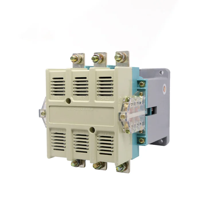
Capacitor-Duty Contactors
For automatic low-voltage power factor correction, a dedicated
بنك المكثفات is commonly used. It is designed to handle capacitor switching stress and often includes pre-charging or damping features to reduce inrush current. Using an ordinary contactor for capacitor switching may lead to:- Contact welding
- Excessive arcing
- Short service life
- Controller faults
- Unreliable stage operation
Power Factor Controllers
The controller is the “brain” of an automatic capacitor bank. A good controller should provide stable switching logic and useful protection or alarm functions.
Important controller features include:- Adjustable target power factor
- Step recognition
- Switching delay settings
- Overvoltage and undervoltage alarms
- Harmonic or temperature alarms, if available
- Manual and automatic operation modes
- Clear display of system values
Thyristor Switches
Thyristor switching is preferred when fast response is required. Since there are no mechanical contacts, there is no contact wear. It can also reduce switching transients when properly designed.
However, thyristor systems produce heat and require proper cooling. They are also more expensive than contactor-switched banks.Switching Method Comparison
| Switching Method | الأفضل لـ | المزايا | Limitations |
|---|---|---|---|
| Capacitor contactor | Normal automatic PFC | Cost-effective, familiar, reliable | Not suitable for very fast load changes |
| Thyristor switch | Dynamic loads | Fast response, no mechanical wear | Higher cost, needs good cooling |
| Vacuum contactor or breaker | MV/HV capacitor banks | Suitable for higher voltage systems | Requires engineered protection and control |
| Fixed switch/disconnector | Constant loads | Simple and economical | No automatic adjustment |
Check Protection, Safety, and Cabinet Design

A capacitor bank stores electrical energy and operates under thermal and electrical stress. Protection design is not decorative; it directly affects safety and service life.
Essential Protection Components
Depending on voltage level and system design, a capacitor bank may require:
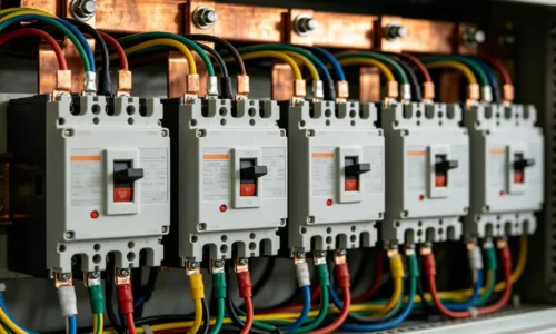
- Fuses or molded case circuit breakers
- Discharge resistors
- Surge protection devices
- Overpressure protection
- Temperature monitoring
- الحماية من الجهد الزائد والجهد المنخفض
- Harmonic or overload protection
- Unbalance protection for high-voltage banks
- Door interlocks and warning labels
- Proper grounding
Thermal Design and Ventilation
Capacitors are temperature-sensitive. Heat accelerates aging and reduces service life. A cabinet installed in a hot electrical room with poor airflow may fail much earlier than expected, even if the electrical sizing is correct.
Good cabinet design should consider: – Air inlet and outlet placement – Fan capacity, if forced cooling is used – Separation between reactors and capacitors – Cable heat dissipation – Ambient temperature limits – Dust filters and maintenance access Reactors can run hot, so placing them too close to capacitor units is a common design weakness.Discharge Time and Safe Maintenance
Capacitors can retain charge after disconnection. Discharge resistors reduce voltage to a safe level within a specified time, but technicians should still verify absence of voltage before touching terminals.
Safe maintenance should include lockout/tagout procedures, waiting time after disconnection, voltage testing, and visual inspection. This is particularly important in high-voltage capacitor banks, where stored energy is much greater.Evaluate the Installation Environment
Even a well-selected capacitor bank can perform poorly in the wrong environment.
درجة الحرارة المحيطة
High ambient temperature is one of the most common causes of capacitor aging. If the capacitor bank is installed near transformers, boilers, direct sunlight, or poorly ventilated rooms, derating may be needed.
Altitude and Humidity
At high altitude, air density is lower, which affects cooling and insulation performance. In humid environments, corrosion and insulation degradation become greater concerns.
For coastal or chemical plants, enclosure material, coating, and internal component protection should be reviewed carefully.Dust, Vibration, and Chemical Exposure
Dust can block ventilation filters and coat insulation surfaces. Vibration can loosen terminals. Chemical vapors can corrode copper, aluminum, and electronic boards.
In harsh environments, ask about:- Enclosure IP rating
- Anti-corrosion treatment
- Forced ventilation design
- Space heaters or anti-condensation measures
- Terminal locking methods
- Maintenance access
A Practical Step-by-Step Selection Checklist

The following checklist gives a practical path from problem identification to final purchase.
- Collect utility bills and demand data
- Confirm system voltage and frequency
- Measure existing power factor
- Define the target power factor
- Calculate required kVAr
- Review load stability
- Check for nonlinear loads
- Measure harmonic distortion if needed
- Select the capacitor bank type
- Choose switching and protection components
- Evaluate installation environment
- Review supplier documentation
- Set up a maintenance schedule
الأسئلة الشائعة
Can a capacitor bank reduce electricity bills in every facility?
Not always. A capacitor bank can reduce costs when the utility tariff includes power factor penalties, reactive demand charges, or kVA-based billing. If a facility is billed only by active energy consumption in kWh and already has a good power factor, the financial savings may be limited. The technical benefit should be compared with the investment cost before purchase.
How often should capacitor banks be inspected?
Inspection frequency depends on the environment and operating duty. In clean and moderate conditions, routine visual checks may be done quarterly or semiannually. In hot, dusty, or heavy industrial sites, inspections should be more frequent. Useful maintenance tasks include checking cabinet temperature, fan operation, contactor condition, controller alarms, fuse status, terminal tightness, and capacitance values.
What happens if the capacitor bank is too large?
An oversized capacitor bank can push the system into a leading power factor, especially during low-load periods. This may cause voltage rise, unstable automatic switching, nuisance trips, generator control issues, and possible utility compliance problems. For variable loads, staged automatic compensation is usually safer than one large fixed capacitor bank.